| Author |
Message |
herd
Joined: Sep 18, 2021
Posts: 4
Location: herd
|
 Posted: Sat Sep 18, 2021 8:19 am Post subject:
troubleshoot twin T? kick monotribe/dr110 Posted: Sat Sep 18, 2021 8:19 am Post subject:
troubleshoot twin T? kick monotribe/dr110 |
  |
|
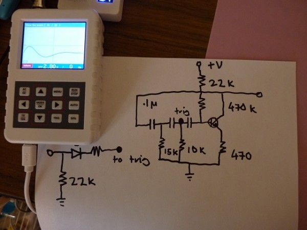
this circuit differs from the monotribe kick with a 10k resistor replacing a 15k resistor (parallel to the other 15k resistor). i noticed this substitution took the peak almost to the rail instead of halfway and i was pretty happy about that.
so i put my parts away to experiment with some other circuits, and since then, every time i build it, i get a different result than the lovely attack contour pictured in the scope - the first 90 degrees is extremely rapid, and the second 90 bulges a bit.
having looked at wavs of analog kicks for decades, i've seen both contours before, and i know which one i want.
this is pretty distressing. possible yet impracticable solutions include, photographing the breadboard before disassembly, and saving the components i used originally for this specific circuit, which i will never ever not do again.
i've been through my components for hours, substituting them with the small assortment i use for breadboarding, wondering about possible errors i may have made. my resistors are all pretty good tolerance and even swapping them out with different values elicits the same crappy contour instead of the pure goaled i had. i've tried shorting it out at various points and trying to discern if an error had achieved the good result. unfortunately, i'm not too hot at capturing waveforms with my fnirsi pro and illustrating the "bad" contour is beyond my ability.
if anyone has any insight into what portion of the circuit affects the first quadrant, i'd love to hear about it.
as a more general enquiry which is certainly secondary to the first, while i modded a dr110 back in the 90s and have been through every comment about anything related to this circuit in the years since, i would love to see some exposition on it in a more general sense -
i'm not sure if it's a twin T or not. most twin T circuits use opamps instead of transistors, and discussion of the last is rare. but transistors are much less challenging for a novice to experiment with.
i'd like to see an educational breakdown explaining the circuit, as the grid arrangement is difficult to fathom for this novice.. it looks like current would flow all over the place. it would be nice to see an overview of how desirable parameters can be used - eg. how to really add a longer decay, as the monotribe mod for pitch glide can't really be validated in the two periods it oscillates for.
my goal this morning was to try and boost the oscillation with a darlington pair (then hopefully restrain it with the usual modification targets), so i've done a fair bit of bootstrapping but one is defeated again and again in the punishing manner so that little comprehension is gained. it would be nice to build one analog drum machine before my eyes and hands go.
what did i do wrong that made it good for me?
| Description: |
|
| Filesize: |
92.17 KB |
| Viewed: |
105 Time(s) |
| This image has been reduced to fit the page. Click on it to enlarge. |
|
|
|
|
Back to top
|
|
 |
herd
Joined: Sep 18, 2021
Posts: 4
Location: herd
|
| Posted: Sat Sep 18, 2021 11:26 am Post subject:
|
|
|
i'm not sure if i've "solved" this issue or not -
i'm using a "lowest price first" ebay breadboard, and it seems that after, 5 weekends of use, there is absolutely no function. i'm finding at least three points in the circuit that aren't connecting unless i hold them with my finger. it was all fine last weekend, it seems as if the springiness has entirely given out between then and now like some sore of existential nightmare.
while adding this doesn't help to solicit more information concerning the circuit, it does serve as a warning to other aspirants, doom is the way of the ebay breadboard. at least, some order of frustrating, finite term doom. |
|
|
Back to top
|
|
|
herd
Joined: Sep 18, 2021
Posts: 4
Location: herd
|
| Posted: Sat Sep 18, 2021 1:16 pm Post subject:
|
|
|
attack contour solved - replacing the 22k running to +V with a 4.6k creates the desired more lissajous attack contour shown in the scope instead of the almost rectangular not good shape. i have yet to observe the other effects of changing this resistor. the not good shape looks like the very compressed response that seems to be more popular and seems a trivial tonal option to include.
also observed that increasing the second capacitor (two .1u in parallel because that's what i have) the attack contour completely loses the sharp transition, really beaut. adding the second transistor had no visible effect 
i also noticed that moving the output a few places back in the capacitor chain produces another very familiar contour. a relatively diminuitive attack 180 extends into a lengthy, wobbly almost triangular 180-360 of greater amplitude. nothing good but very vintage looking. (sorry i don't use phone or any devices that are easy/convenient for imaging).
for the time being, the breadboard can be used with some care to angle the leads before insertion.
larger nonpolarised capacitors in the mail, interested to see if the pitch glide mod suggested for the monotribe is functional. |
|
|
Back to top
|
|
|
|

 Forum index » DIY Hardware and Software

