| Author |
Message |
volta
Joined: Apr 04, 2022
Posts: 2
Location: EU
|
 Posted: Fri May 05, 2023 10:27 am Post subject:
4069UB triangle waves 40106 - Buffer stages Posted: Fri May 05, 2023 10:27 am Post subject:
4069UB triangle waves 40106 - Buffer stages |
  |
|
Hi everyone!!
I'm new to this forum 
I've been experimenting with sound circuits based on CMOS, I came across this tutorial from Eliot Williams (Logic Noise)
https://hackaday.com/2015/03/09/logic-noise-sawing-away-with-analog-waveforms/
I'm building an instrument using triangle waves from a 40106 and sending them to a 4069 for buffering. I don't have much knowledge of electronics and am still learning, but I'm thinking of sending each triangle oscillator (3 or more) to a different inverter available on the 4069. connecting a 100k resistor to the input and a 100k resistor to the feedback. Is it a good idea to do it separately? or I should just use one inverter to mix and buffer it all like the active mixer presented here: https://hackaday.com/2015/07/02/logic-noise-ping-pong-stereo-mixers-and-more/
I thought of using them separately because their are going to be so many inverters unused and I'm not thinking to overdriving them.
Should I add 1uf capacitors before the triangle waves enter the 4069? Or is it unnecessary in this case?
Also, I'm wondering what's the best way to add independent volumes to each oscillator, if it should be before or after the buffer.
Sorry for so many questions, I'm going to continue to experiment with several setups of this. Thank you! |
|
|
Back to top
|
|
 |
ianbax
Joined: Apr 20, 2022
Posts: 42
Location: Sheffield, UK
|
|
|
Back to top
|
|
|
PHOBoS

Joined: Jan 14, 2010
Posts: 5904
Location: Moon Base
Audio files: 709
|
| Posted: Tue May 09, 2023 10:51 am Post subject:
|
|
|
 
| ianbax wrote: | | I *think* if you're mixing them a buffer for each one (i.e. one inverter from the 4069) is essential, otherwise they will interact. Like you said you've got inverters to spare and if I've learned one thing on my electronics journey it's that buffers are good! |
With a regular opamp configured as a (inverting) summing amp there shouldn't be any interaction.
However, a 4069 is not a regular opamp, and on top of that you're directly connecting to the timing capacitor of an oscillator.
Any change in load on this capacitor will alter the frequency of the oscillator which is already a good reason to buffer it.
I don't have much experience with the 4069 though, I did mess around a bit on a breadboard with a wasp clone
and maybe some other simple circuits but that's about it.
I think the 4069 has some non-linearity and a limited signal voltage range which can make it an interesting choice
especially for something simple like this.
That circuit looks good to me. Could test with and without buffers and see what happens.
| volta wrote: | | Should I add 1uf capacitors before the triangle waves enter the 4069? Or is it unnecessary in this case? |
You shouldn't need a cap between the triangle and the buffers and if you buffer with a 4069 and then mix with another 4069 you
probably won't need any caps but I am not sure. Maybe you do if you add the pots but then you probably have to place caps before
and after the pot. You should definitely put one on the final output though.
_________________
"My perf, it's full of holes!"
http://phobos.000space.com/
SoundCloud BandCamp MixCloud Stickney Synthyards Captain Collider Twitch YouTube |
|
|
Back to top
|
|
|
volta
Joined: Apr 04, 2022
Posts: 2
Location: EU
|
| Posted: Wed May 10, 2023 5:59 am Post subject:
|
|
|
Thank you ianbax and phobos!!
I experimented both ideas that I talked on the first post to understand them better and I liked the result of using a buffer for each one with 4069!
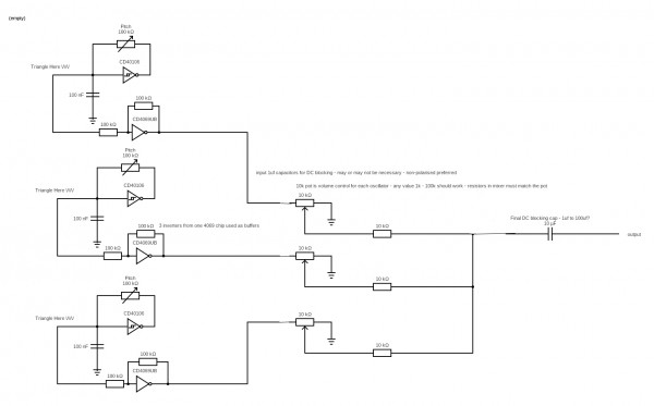
I breadboard the circuit with 3 oscillators, triangles waves to separates buffers on 4069, and then volumes potentiometers and resistors mixing and output cap. (I changed some things on your image Ianbax to explain this version, thank you for sharing the draft). I tried to use another inverter from the 4069 as a summing amp like you said, but I compared between the two versions and I prefered without it, because when the volumes are all down, I notice a lot of noise on the sound when outputting to my mixer and PA, the circuit sound more quieter and smooth when I don't use that part. I also added decoupling caps on power, 2 caps of 100 uf and 100nf on the power pin of every chip and it helped with the noise a bit.
| Quote: | The one thing you may want to play around with is the output DC blocking capacitor - I think I misread the Logic Noise article and put a huge capacitor in there (10uf I think, maybe it was more) and I ran in to trouble with impendence plugging into a guitar amp (buffered mixer fine) - there's a thread on it!
|
I used the 10 uf and haven't got problems it, but I would like to understand better this kind of problems of impendance, something I need to search more about.
| Quote: | With a regular opamp configured as a (inverting) summing amp there shouldn't be any interaction.
|
Maybe I should use an opamp to do this kind of buffering and mixing instead of the 4069, would it be better in terms of noise or connection to other circuits like filters? I have done some mixers with Opamps like tl072 and others, but I saw this tutorial of Elliot and gave it a try.
If I want to connect this kind of circuit to a filter like a WSG filter should it be a problem of connecting the mixer of resistors directly to the input of it?
I'm going to experiment more! Thank you all!!
| Description: |
|
| Filesize: |
110.41 KB |
| Viewed: |
277 Time(s) |
| This image has been reduced to fit the page. Click on it to enlarge. |
|
|
|
|
Back to top
|
|
|
ianbax
Joined: Apr 20, 2022
Posts: 42
Location: Sheffield, UK
|
| Posted: Thu May 11, 2023 5:09 am Post subject:
|
|
|
No problem - my pleasure. Glad you got it working.
Interesting about the summing mixer - I've used that design to mix the square waves from a 40106 but I suppose with the triangle waves already buffered individually the active mixer is just over-engineering. A passive mixer (as you've built) works just fine and as you say, a lot cleaner.
Last edited by ianbax on Thu May 11, 2023 5:20 am; edited 1 time in total |
|
|
Back to top
|
|
|
ianbax
Joined: Apr 20, 2022
Posts: 42
Location: Sheffield, UK
|
| Posted: Thu May 11, 2023 5:19 am Post subject:
|
|
|
and just on the 4069 as op amp - perhaps others may find this thread and find it useful
It crops up in Ellliot Williams' logic noise here:
https://hackaday.com/2015/03/09/logic-noise-sawing-away-with-analog-waveforms/
Where he goes into what makes the unbuffered version work as an amplifier - one with a pleasing distortion curve - so as Phobos says, perhaps not the first choice for a hi-fi (well, relatively) mixer.
Incidentally Nicolas Collins recommends the 4049 chip (which was actually what I've used) and claims they're virtually identical for hacking purposes. If you google a couple of guitar FX forums delve into whether they're different.
The audio-phool also recommends one in this video on active filters
https://www.youtube.com/watch?v=aqfyRUVSq9I
About twelve minutes in he basically says if you need something like an op-amp that's been given a virtual ground 1/2 of VCC then the 4069 is basically that in a chip. That's what attracted me initially - having a single supply and getting to know other CMOS chips in my project it seemed easier than getting into op amps.
Elliot points out that if a design (like a simple filter) is an op amp with the positive terminal tied to ground then the 4069UB (or 4049UB) can substitute in - probably with some unpredictable results! |
|
|
Back to top
|
|
|
Top Top

Joined: Feb 02, 2010
Posts: 266
Location: California
|
| Posted: Sat Jun 03, 2023 1:02 am Post subject:
|
|
|
I've used 4069UB for filters and mixer uses many times. I built a six channel mixer with 4069 twin T band pass filters on every channel, then a 4069 summing amplifier stage, and even a spring reverb driven and amplified by 4069UB.
They do have a rounded squaring to them that sounds nice. It's not accurate, quiet, or hi fi for sure!
_________________
∆ A.M.P. ESOTERIC ELECTRONICS ∆ |
|
|
Back to top
|
|
|
PHOBoS
Joined: Jan 14, 2010
Posts: 5904
Location: Moon Base
Audio files: 709
|
| Posted: Sat Jun 03, 2023 2:42 am Post subject:
|
|
|
oh right, filters. Now that you mention it I did actually use the 4069 for the RGB Shroom drum.
@ianbax thanks for all the info! I really should look into it a bit more, it's an interesting chip.
I wonder if it could do something interesting for video signals as well, since CMOS is generally very suitable for high frequencies
and video signals also have a rather low amplitude.
_________________
"My perf, it's full of holes!"
http://phobos.000space.com/
SoundCloud BandCamp MixCloud Stickney Synthyards Captain Collider Twitch YouTube |
|
|
Back to top
|
|
|
|

 Forum index » DIY Hardware and Software » Lunettas - circuits inspired by Stanley Lunetta


