| Front Page | Radio | Media | Forum | Wiki | Links |

and electronic music
|
|
Dedicated to
experimental electro-acoustic and electronic music |
|
|
|
|
|||||||||||||
 Forum index » DIY Hardware and Software » Microcontrollers and Programmable Logic Forum index » DIY Hardware and Software » Microcontrollers and Programmable Logic |
|
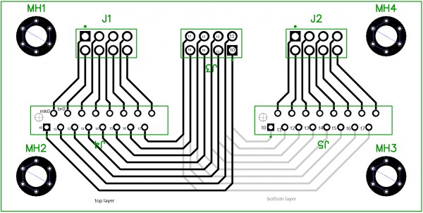
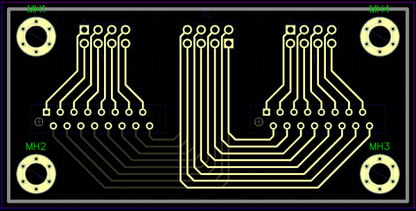
fatar keybed adapter - identify pin-out
|
 
|
Moderators: State Machine
Page 1 of 1 [3 Posts] |
View unread posts View new posts in the last week Mark the topic unread :: View previous topic :: View next topic |
|
|
Moderators: State Machine
Page 1 of 1 [3 Posts] |
View unread posts View new posts in the last week Mark the topic unread :: View previous topic :: View next topic |
|
Forum index » DIY Hardware and Software » Microcontrollers and Programmable Logic |
|
You cannot post new topics in this forum You cannot reply to topics in this forum You cannot edit your posts in this forum You cannot delete your posts in this forum You cannot vote in polls in this forum You cannot attach files in this forum You can download files in this forum |