| Author |
Message |
mosc
Site Admin

Joined: Jan 31, 2003
Posts: 18234
Location: Durham, NC
Audio files: 220
G2 patch files: 60
|
|
|
Back to top
|
|
 |
Scott Stites
Janitor


Joined: Dec 23, 2005
Posts: 4127
Location: Mount Hope, KS USA
Audio files: 96
|
 Posted: Sun Jan 08, 2006 4:51 pm Post subject: Posted: Sun Jan 08, 2006 4:51 pm Post subject:
|
  |
|
Pretty cool, Howard! The ability to input signals to be sequenced is a very powerful tool. I imagine this sequencer blew minds on a regular basis.
Ken Stone now has the sequential switch that performs that function also. It has a neat method for sliding bipolar signals through a 4051.
http://www.cgs.synth.net/modules/cgs28_seq_switch.html
I've got a file showing the current layout of the sequencer I'm working on, it's in in FPD format, which is used by Schaeffer Front Panel Express. I can post it, but if you don't have that program, it wouldn't do much good.
It's a 32 step sequencer made up of four individual 8 step sequencers. I've got internal logic that converts it into 4X8, 16X1/8X2, 16X1/16X1, 8X2/16X1, 24X1/8X1, 8X1/24X1 and 32X1 modes.
I've got a four channel quantizer on it as well. The quantizer is adapted from the ARP style quantizer.
Each 'row' is capable of being driven from a different clock. Each row, therefore, can have its own time signature. When in the chained modes, the sequence adapts to the time signature of the current row. In parallel modes, each row can bubble along at its own time signature. In the 8X4 mode, one could use a second sequencer or quadrature clock to drive multiponic arabesque sequences.
I've got a couple of modes that I've dubbed as 'Async 1' and 'Async 2' that sabotage the 'normal' handoff between rows. When driven from different clocks, the async functions basically turn the row selection into a free-for-all; the sequencer in the chain that hits the end of its count first gets to make the determination that the active row needs to 'hand off'. One mode forces the selected row to reset, the other lets it start up at whatever its internal count is.
I tried attaching a sample of half the sequencer (16 steps) in that mode to this message, but it didn't work out. I'm on dial-up, and by the time the thing loaded, the forum asked me for my password, and I couldn't get to the uploaded attachemtn. So, I've got a link to it here instead:
http://mypeoplepc.com/members/scottnoanh/sitebuildercontent/sitebuilderfiles/async_examples.mp3
Though there are 16 steps in each sequence example, the overall repeating pattern is much longer than 16 steps. One row's clock is a divide by 2 division of the other row's clock. Each row is controlling a separate voice.
Cheers,
Scott |
|
|
Back to top
|
|
|
deknow

Joined: Sep 15, 2004
Posts: 1307
Location: Leominster, MA (USA)
G2 patch files: 15
|
| Posted: Sun Jan 08, 2006 5:18 pm Post subject:
|
|
|
howard, what a flexible sequencer! it reminds me very much of the sam16 (i think the best available step sequencer...i wish i had a few).
http://www.s-n-d.com/sam16e.html
deknow |
|
|
Back to top
|
|
|
mosc
Site Admin
Joined: Jan 31, 2003
Posts: 18234
Location: Durham, NC
Audio files: 220
G2 patch files: 60
|
| Posted: Sun Jan 08, 2006 7:29 pm Post subject:
|
|
|
Don't know why you would have a problem posting that file as an attachment unless you are on a dialup or very slow uplink. There is approximately a 10 minute timeout for HTTP connections. The file size limit on the forum is 10 MB.
_________________
--Howard
my music and other stuff |
|
|
Back to top
|
|
|
dont
Joined: Mar 20, 2006
Posts: 5
Location: UK
|
| Posted: Wed Mar 22, 2006 4:02 pm Post subject:
|
|
|
| This looks fantastic. Could you point me to any of your music in which it makes an appearance? I can imagine some beautiful wavetable-like arpeggios coming from it. |
|
|
Back to top
|
|
|
mosc
Site Admin
Joined: Jan 31, 2003
Posts: 18234
Location: Durham, NC
Audio files: 220
G2 patch files: 60
|
| Posted: Thu Mar 23, 2006 7:57 am Post subject:
|
|
|
I don't have any music in digital format that was made with that beast. It's all on 1/4" reel to reel tape. Someday, I need to devote a month and convert all my tapes to digital.
Oh, maybe it would just be easier to fix the thing and make some music with the Moog.
Anyhow, if you want to hear some of my more recent stuff, check the link below in my signature. The posts with attachments are where the mp3s are attached.
_________________
--Howard
my music and other stuff |
|
|
Back to top
|
|
|
Macaba
Joined: Jul 13, 2005
Posts: 160
Location: UK
|
| Posted: Sun Apr 09, 2006 4:16 am Post subject:
|
|
|
| Which IC's is this thing based on? I'd love to know how you got all that versatility with which IC's. |
|
|
Back to top
|
|
|
mosc
Site Admin
Joined: Jan 31, 2003
Posts: 18234
Location: Durham, NC
Audio files: 220
G2 patch files: 60
|
| Posted: Sun Apr 09, 2006 5:48 am Post subject:
|
|
|
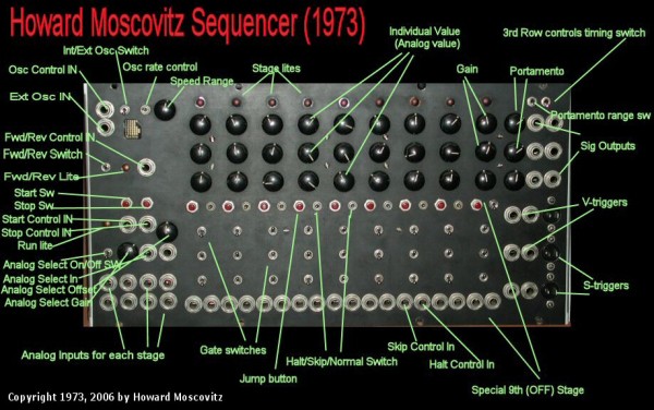
The heart of the beast is a binary up/down counter. I think it was something like the 74C193. The other big deal with this sequencer was the use of an analog switch IC. This was when they first came out. I don't remember the number but it is similar to the ADG408
The rest of the chips were standard TTL (74C stuff), Op Amps and the like. The clock was a 555 oscillator - not the best thing. Most of the time I used an external oscillator.
Thanks for asking. I'm having fun just thinging about this. 
_________________
--Howard
my music and other stuff |
|
|
Back to top
|
|
|
bachus

Joined: Feb 29, 2004
Posts: 2922
Location: Up in that tree over there.
Audio files: 5
|
| Posted: Mon Apr 10, 2006 7:15 pm Post subject:
|
|
|
Very cool indeed mosc.
_________________
The question is not whether they can talk or reason, but whether they can suffer. -- Jeremy Bentham |
|
|
Back to top
|
|
|
Macaba
Joined: Jul 13, 2005
Posts: 160
Location: UK
|
| Posted: Thu Apr 13, 2006 11:44 am Post subject:
|
|
|
| mosc wrote: |
Thanks for asking. I'm having fun just thinging about this. |
Well i'm really interested in this sequencer and reviving it. I have the resources to design and make decent PCB's. I'm just currently learning the skill of designing circuits, which I suppose is a never-ending process. Perhaps with your schematical input, we can bring a 21st century version to life? Apologies if i've overstepped my boundaries.
Mac |
|
|
Back to top
|
|
|
mosc
Site Admin
Joined: Jan 31, 2003
Posts: 18234
Location: Durham, NC
Audio files: 220
G2 patch files: 60
|
| Posted: Thu Apr 13, 2006 11:58 am Post subject:
|
|
|
Great. Thanks for the offer. I accept.
I was hoping that someday someone would offer to do this. I suggested this to some other people in the past, but nobody was able to commit the time, or the money to put together the parts.
It's a complicated beast; I think it had 67 ICs. I put the circuits on two protoboards. Maybe we could get it on one board with modern techniques. To bring it up to date, it needs some circuitry to enable 2 or more to be daisy chained or operated in parallel. Also, something like the Moog sequential switch should be built with this. I never got around to building that.
Another thing to is - should we move to a more modern technology, with LED collared rotary encoders and preset memories. That's a completely new item. There are members here that have the chops to design the embedded processors to pull that off. It would be much more expensive and a lot more of a chore to wire up. Every one of the trigger switches would become a push button with a lite - preferably a two or three color lite.
_________________
--Howard
my music and other stuff |
|
|
Back to top
|
|
|
Macaba
Joined: Jul 13, 2005
Posts: 160
Location: UK
|
| Posted: Thu Apr 13, 2006 12:32 pm Post subject:
|
|
|
67 IC's!!! I'm astounded. Wasn't expecting that many! Perhaps with new IC's, this can be reduced, but with the same or more features. I would probably use SMT, as hand soldering SMT is easy (ok, to my young eyes).
I will say this then- I probably won't have a 100% idea how it works if you give me a schematic, but designing the boards should be fine.
We can use PIC's for digital control aspects. It is quite easy to extend a small 20 pin PIC to have many outputs, by using parallel shift registers. (You pulse a pin into the shift register to get your desired pattern, then pulse the parallel one to transfer the pattern to the outputs. This way, you don't see any pulsing on the outputs, just a smooth change.) Obviously, you need more clock cycles to acheive a output result. |
|
|
Back to top
|
|
|
mosc
Site Admin
Joined: Jan 31, 2003
Posts: 18234
Location: Durham, NC
Audio files: 220
G2 patch files: 60
|
| Posted: Thu Apr 13, 2006 12:43 pm Post subject:
|
|
|
I used single op amp chips; nowadays there are the quad packages. That'll save a lot of chips right there. I think you said you were simulating circuits. What simulator do you use? Does it work with a schematic capture program? Do you think it is possible for multiple people to collaborate easilly on such a project?
_________________
--Howard
my music and other stuff |
|
|
Back to top
|
|
|
jksuperstar

Joined: Aug 20, 2004
Posts: 2503
Location: Denver
Audio files: 1
G2 patch files: 18
|
| Posted: Thu Apr 13, 2006 1:14 pm Post subject:
|
|
|
The stepping & controls could be done with a CPLD or the like, a 40-pin part could handle all the counting, stepping, clocks, and controls. A little microcontroller would also do fine (in fact, it give you a lot of capability for saving, or multiple, simultaneous tracks). The outskirts could be analog muxes/switches/mixers. There are digitally controlled versions of most of these nowadays.
If it were up to me, I'd break up the system into at least two components: 1 for interface, 1 for functions. Maybe 1 for digital functions, multiple for analog functions (multiple tracks). That way, you could put the sequncer in a small box and make it midi controlled, with all the control coming from the users repertoir of control surfaces. It also allows for anyone to design the "front-end" to suit thier needs. Last, I'd add MIDI, so it can be a controller of itself (midi sequencer, or recording). |
|
|
Back to top
|
|
|
mosc
Site Admin
Joined: Jan 31, 2003
Posts: 18234
Location: Durham, NC
Audio files: 220
G2 patch files: 60
|
| Posted: Thu Apr 13, 2006 1:42 pm Post subject:
|
|
|
Good input. The thing not to loose track of is that this sequencer is very much a playable device. You play it like a keyboard. The jump buttons, the trigger switches, the fwd/rev switch, the pots, all make an instruments. There are lots of nice sequencers made today with great features, but they aren't really playable.
So, I'd rather have no memory and keep the interface than have to adjust it to support the features of memory.
Perhaps I don't understand what you are saying, JK.
BTW, I thought I memtioned it, but all three rows are made with analog MUXes. These are connected to a single 74C193. Very simple actually. The hard part was actuall the halt, jump, and skip features - and they aren't that hard.
BTW, the Zeit Sequencer might be an improvement over my sequencer, except that it is digital. You can't plug 8 FM radios into it an switch between them in real time. (I don't think. I'll see it at electro-music 2006 )
_________________
--Howard
my music and other stuff |
|
|
Back to top
|
|
|
jksuperstar
Joined: Aug 20, 2004
Posts: 2503
Location: Denver
Audio files: 1
G2 patch files: 18
|
| Posted: Thu Apr 13, 2006 2:14 pm Post subject:
|
|
|
No, I was just thinking in terms of design, and particularly the PCBs (or parts of it). Having 1 microcontroller, the sequencer could easily handle MIDI, a storage card if desired, or just a flash/EEPROM part. It could also handle several tracks simultaneously. (my little box here has all of these features).
http://electro-music.com/forum/viewtopic.php?highlight=midi+controller&t=7323
But, if designed right, it could handle all the analog parts of your design, or could handle 2, or even 4 of them, so you could play multiple tracks.
I understand that having an interface is key to using it, but if a switch was located right on the box, or off on your own BCR2000, or your G2, it really wouldn't matter. The design would allow the user to make that choice (which may be important, for example, you build the box to have controls over your sequencer, but add a second analog part to it. Now you can use your other controller for the second track.)
Maybe I'm thinking to modularly, instead of 1-box, 1-instrument. I wouldn't want it to be too difficult to build, or overdesigned for no reason. But I would suggest a microcontroller, and would even offer the code for it. I use Atmel AVR parts, since they're designed for high languages, have efficient code, and enough people use them that there's prolific libraries in existance.
I mean, if I could build my ideal sequencer, it would have an embedded version of KeyKit running in it's core. That could then control an analog mux system like you have, with a program running to respond like your sequencer does, but still be stable like hardware is. And still always be expandable. But that's neither here nor there... |
|
|
Back to top
|
|
|
Macaba
Joined: Jul 13, 2005
Posts: 160
Location: UK
|
| Posted: Fri Apr 14, 2006 4:28 am Post subject:
|
|
|
| mosc wrote: | | I used single op amp chips; nowadays there are the quad packages. That'll save a lot of chips right there. I think you said you were simulating circuits. What simulator do you use? Does it work with a schematic capture program? Do you think it is possible for multiple people to collaborate easilly on such a project? |
I use the Proteus package. This has two main programs. You draw up your schematic in ISIS and simulate it. When you are happy, ISIS imports the netlist into ARES which is the PCB design program and because it has the netlist, it makes sure that you are connecting the right pads, and in the high end expensive version, it lays down the design for you.  (I *think* so. The site isn't too clear on this) (I *think* so. The site isn't too clear on this)
I would also agree with jksuperstar's idea of making the design modular. We can make the muxes and their circuitry a module, so the control board (that has the halt/skip/etc features) can support upto 3 (or more) but you could opt for 1 row of 8 if you only wanted a smaller portable sequencer.
In terms of collaboration, making the design more modular, with a standardised bus connection would help in this I think.
'So, I'd rather have no memory and keep the interface than have to adjust it to support the features of memory. '
Yes, wholeheartedly agree, lets make a product that is less conventional, but ultimately better. But I'm sure we could put memory features in, provided you guys can handle the massive complications i'm sure this would provide. Just you let you know, I can program PIC's upto 18F series, so its fine if you want to use AVR's but I can't prototype it that effectively, UNLESS the programmer for it is as simple as the PIC programmers, so I can build my own. |
|
|
Back to top
|
|
|
mosc
Site Admin
Joined: Jan 31, 2003
Posts: 18234
Location: Durham, NC
Audio files: 220
G2 patch files: 60
|
| Posted: Fri Apr 14, 2006 9:13 am Post subject:
|
|
|
Here's what I'm having problems understanding. I guess a pic could be used for logic to do the 1 of 8 selection - no problem with that but I'm not sure it's not over kill. If we make the device with memory, what would be memorized? If you are going to memorize the settings of the knobs and the trigger switches then you need rotary encoders and and a different mechaniism for the triggers. My sequencer uses a big OR gate made with diodes and a pull up resistor.
As I see it, once you make the jump to store the triggers and voltages, then you make a huge jump. It's more than just adding a module. Am I missing something?
_________________
--Howard
my music and other stuff |
|
|
Back to top
|
|
|
jksuperstar
Joined: Aug 20, 2004
Posts: 2503
Location: Denver
Audio files: 1
G2 patch files: 18
|
| Posted: Fri Apr 14, 2006 10:43 am Post subject:
|
|
|
Maybe I just dove off your diving board created with this comment:
| Quote: | | Another thing to is - should we move to a more modern technology, with LED collared rotary encoders and preset memories. That's a completely new item. There are members here that have the chops to design the embedded processors to pull that off. It would be much more expensive and a lot more of a chore to wire up. Every one of the trigger switches would become a push button with a lite - preferably a two or three color lite. |
Once you take that step, which it is a big one, you have to seperate the interface from the analog functions, and once you do that, adding all the other stuff I mentioned comes nearly free (software is free, isn't it?  ) ) |
|
|
Back to top
|
|
|
mosc
Site Admin
Joined: Jan 31, 2003
Posts: 18234
Location: Durham, NC
Audio files: 220
G2 patch files: 60
|
| Posted: Fri Apr 14, 2006 12:16 pm Post subject:
|
|
|
I guess I am on the right track with my understanding then. I guess I shouldn't have jumped onto the rotary encoder path, but how would one go about making something with like 24 rotary encoders and switches?
I guess you would have some sort of interupt driven system. Everytime an encoder is moved it sends a pulse to the controller. What kind of address decoder would you use? Seems like a big job...
Hmmm... If you go that route, then you end up reinventing the P3 or the Zeit or something.
OK, well, it is good to think things through before starting a project.
_________________
--Howard
my music and other stuff |
|
|
Back to top
|
|
|
deknow
Joined: Sep 15, 2004
Posts: 1307
Location: Leominster, MA (USA)
G2 patch files: 15
|
| Posted: Sat Apr 15, 2006 11:58 pm Post subject:
|
|
|
...i've been thinking about a similar project. as much as i want to, i can't seem to get away from the idea that behringer bcr could be taken out of it's case, and custom mounted (usb connection and all) in anything for probably less money than buying the knobs, led collars, buttons, etc. is this just nuts?
deknow |
|
|
Back to top
|
|
|
Macaba
Joined: Jul 13, 2005
Posts: 160
Location: UK
|
| Posted: Wed May 03, 2006 12:24 am Post subject:
|
|
|
| Hey, i just randomly googled for a counter with up/down control, and I stumbled upon the 4029 CMOS chip, is this something you use? If not, perhaps consider it, it certainly eliminates the parts count of doing a 'discrete' version. |
|
|
Back to top
|
|
|
mosc
Site Admin
Joined: Jan 31, 2003
Posts: 18234
Location: Durham, NC
Audio files: 220
G2 patch files: 60
|
| Posted: Wed May 03, 2006 5:40 am Post subject:
|
|
|
Yes, the 74C193 and the 4029 are pretty much the same, but the 4029 has the advantage of the built-in up-down circuitry. The 193 has separate up and down clocks which might be usefull in some circumstances. For a step sequencer, I think the 4029 is a better choice.
_________________
--Howard
my music and other stuff |
|
|
Back to top
|
|
|
george
Joined: Aug 06, 2006
Posts: 1
Location: UK
|
| Posted: Sun Aug 06, 2006 8:26 am Post subject:
|
|
|
Hi! I'm new here, and a bit of a beginner to synthesizers. (Not to electronics though) I was wondering whether this project was still going? I'd love to help, i can read/write schematics, and design pcbs etc. So far this sounds like a really good idea, i'd love to see it finished.
cheers,
George. |
|
|
Back to top
|
|
|
mosc
Site Admin
Joined: Jan 31, 2003
Posts: 18234
Location: Durham, NC
Audio files: 220
G2 patch files: 60
|
| Posted: Sun Aug 06, 2006 6:23 pm Post subject:
|
|
|
Hi, George.
I don't have the schematics anymore. I remember most of the circuits though. There are many ways to recreate this. Unfortunately, I don't have the time or energy to do this project, but I can provide advice and suggestions if anyone would want to recreate this.
_________________
--Howard
my music and other stuff |
|
|
Back to top
|
|
|
|

 Forum index » Artists » Howard Moscovitz