| Author |
Message |
ianbax
Joined: Apr 20, 2022
Posts: 42
Location: Sheffield, UK
|
 Posted: Fri Jun 03, 2022 1:16 pm Post subject:
4093 - Strange Behaviour Posted: Fri Jun 03, 2022 1:16 pm Post subject:
4093 - Strange Behaviour
Subject description: Gated Oscillator built with 4093 NAND gate behaves strangely seeking 'proper' electronic explanation |
  |
|
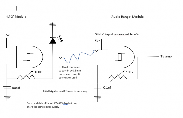
Hello all,
I'll built a bank of slow 'LFO' 4093 oscillators (100k pot, 100uf capacitor) to use as clocks and another bank in audio range (100k pot, 100nf cap).
As per Nicholas Collins and many others, the idea is that the output of the first can be plugged into one side of the 4093 and gate the audio ones.
They're on two separate chips built as 'modules' and I'm using the tip of 3.5mm jacks to make the connections.
The gate input (one side of the 4093) is normaled to 5v (the power supply) so unless a gate is plugged in the audio range oscillator drones away. When I plug in the gate, it works, but the pitch drops quite significantly I think I can even hear a bit of a ramp up rather than a clean switch on and off.
One other thing - on the LFO module there are indicator LEDs - so the output is about a 3v square wave because of the LED voltage drop (it's just wired straight to the output, no separate driver). I thought perhaps I was running too close to the switching threshold of the 4093 but I tried upping the voltage and it was the same.
Now from a bit of reading *I think* I know what's going on - it's some sort of 'loading' and impedance issue - The reason I say that is I seem to have solved the problem by plugging a buffer (either two stages of a 4049 or recently discovered 4050 non-inverting) between the stages i.e. on the gate input of the 4093. I'm just curious what's going on - I didn't think there was an issue of CMOS gates driving other gates - like you'd have to get to trying to drive 20 other gates before fanout limits became an issue (according to my R.A. Penfold book).
Can someone with more advanced electronic knowledge shed any light? I'm kinda hungry for a proper explanation. As I build more modules do I need to think about buffering all gate inputs - say, adding a clock divider from a 4040 or using the 'LFO' to clock a 4017 sequencer. That is potentially an extra IC each time and more connections. Perhaps this only effects oscillator circuits because of the external components (big caps?) involved? |
|
|
Back to top
|
|
 |
PHOBoS

Joined: Jan 14, 2010
Posts: 5947
Location: Moon Base
Audio files: 709
|
Posted: Mon Jun 06, 2022 7:02 am Post subject:
Re: 4093 - Strange Behaviour
Subject description: Gated Oscillator built with 4093 NAND gate behaves strangely seeking 'proper' electronic explanation |
|
|
If the LFOs are at their highest speeds it requires the chip to charge/dicharge the 100uF caps with a higher current, combined with the voltage
drop caused by the LEDs this might be an problem. Also with a 5V supply a 3V logic level is pushing it a bit but since they are schmitt trigger
inputs it should be less of an issue.
A drop in pitch is interesting if you look at what could affect the pitch in the first place. With these kind of oscillators the first thing to
suspect would be the supply voltage and a drop in pitch would suggest a rise in the voltage. Unless there is something funny going on
with the normalling that doesn't seem very likely. Whatever you do to the other input of the NAND gate shouldn't really affect its
frequency (unless you are modulating it with a high frequency). The only other way that I see that could affect it is through the output
of the gate as that is part of the circuit that makes it oscillate. If you load it too much it could affect the frequency.
| ianbax wrote: | | The reason I say that is I seem to have solved the problem by plugging a buffer (either two stages of a 4049 or recently discovered 4050 non-inverting) between the stages i.e. on the gate input of the 4093. |
hmm that's a bit odd as that suggest it is the modulating oscillator that affects the frequency. Can you test it without the LEDs ?
also a schematic might be useful, as I might make the wrong assumptions about how things are connected.
| Quote: | | As I build more modules do I need to think about buffering all gate inputs - say, adding a clock divider from a 4040 or using the 'LFO' to clock a 4017 sequencer. That is potentially an extra IC each time and more connections. Perhaps this only effects oscillator circuits because of the external components (big caps?) involved? |
That shouldn't really be needed for something like this and LED drivers would probably have more effect. That is a downside of using
a 5V supply btw. The chips will have a harder time driving an LED than with something like 12V.
_________________
"My perf, it's full of holes!"
http://phobos.000space.com/
SoundCloud BandCamp MixCloud Stickney Synthyards Captain Collider Twitch YouTube |
|
|
Back to top
|
|
|
ianbax
Joined: Apr 20, 2022
Posts: 42
Location: Sheffield, UK
|
| Posted: Mon Jun 06, 2022 8:37 am Post subject:
|
|
|
Thanks for taking the time Phobos.
Advice taken on 5v supplies - I as thinking ahead to interfacing with an Arduino which is why I plumped for 5v.
As it was within tolerance of the resistors I chose for the LEDs I bumped it up to 9v but got the same result.
It's difficult to take the LED out of the equation with this soldered up version (I only noticed this behaviour after I'd finished the LFO module with a face plate and everything). I'll probably breadboard something up to satisfy my curiosity.
I did breadboard up a quick experiment dividing these LFO clocks with a 4040 and all was well - as you say 3v pushing it but it worked.
I did a schematic (it's a bit crappy - I wasn't sure how to represent the separation of the circuits and their interconnection with a patch lead). As the buffer between the two works the only conclusion I come to is that somehow they interact once connected. I twigged this as in the logic noise series and the article on filters:
https://hackaday.com/2015/03/25/logic-noise-filters-and-drums/#:~:text=Logic%20Noise%20is%20an%20exploration,filter%20with%20a%20single%20part.
in the video (not in the text) Elliot notices his filter 'loading' the oscillator and altering it's pitch - he adds a buffer between the two to solve the problem.
So I've got a solution at least. I've rigged up a 4050 between the input and the gate.
| Description: |
|
| Filesize: |
34.21 KB |
| Viewed: |
3998 Time(s) |

|
| Description: |
|
| Filesize: |
34.21 KB |
| Viewed: |
333 Time(s) |
| This image has been reduced to fit the page. Click on it to enlarge. |
|
|
|
|
Back to top
|
|
|
ianbax
Joined: Apr 20, 2022
Posts: 42
Location: Sheffield, UK
|
| Posted: Mon Jun 06, 2022 9:02 am Post subject:
|
|
|
Reading back - to be super clear. The pitch change is noticed when you switch from the constant 5v (the normalled connection) to the external input (square wave from the 'lfo').
So at 5v constant into one side of the 4093, the oscillation is at a higher pitch than when the square wave is applied.
It could be as simple as the gated square wave is roughly 3v peak to peak and the constant source is 5v but I thought that as long as one side of the 4093 is higher than it's threshold it'll read high and that's that. |
|
|
Back to top
|
|
|
ianbax
Joined: Apr 20, 2022
Posts: 42
Location: Sheffield, UK
|
| Posted: Mon Jun 13, 2022 6:54 am Post subject:
Solved - in a way |
|
|
As a follow up to this - just in case anyone searches for the same problem - after getting p'd off with the complexity of the circuit needing extra ICs to buffer I went 'back to basics' and looked again at oscillator options.
I breadboarded up the 40106 oscillator with a diode on the input to achieve gating which sound wise (and perhaps electrically) is much the same as the 4093 circuit. For whatever reason (internals in the 4093?) the pitch issue is corrected and a much more compact circuit is achievable - a N4148 and resistor on each input rather than an IC.
Diodes as gates - there's schematics everywhere I followed this one:
https://hackaday.com/2015/02/04/logic-noise-sweet-sweet-oscillator-sounds/
No normalling is needed to +5v either as the default of the oscillator is continuous if no signal is connected to the diode. So a bit of wiring saved.
Now I have another issue with switching noise at high frequencies but I think that's an unavoidable consequence of switching a square wave on and off quickly in this fashion. [ |
|
|
Back to top
|
|
|
PHOBoS
Joined: Jan 14, 2010
Posts: 5947
Location: Moon Base
Audio files: 709
|
| Posted: Wed Jun 15, 2022 11:49 am Post subject:
|
|
|
| ianbax wrote: | | It could be as simple as the gated square wave is roughly 3v peak to peak and the constant source is 5v but I thought that as long as one side of the 4093 is higher than it's threshold it'll read high and that's that. |
Yeah, that shouldn't really make a difference as far as I know.
looking at the schematic; did you not use any resistors in series with the LEDs ?
_________________
"My perf, it's full of holes!"
http://phobos.000space.com/
SoundCloud BandCamp MixCloud Stickney Synthyards Captain Collider Twitch YouTube |
|
|
Back to top
|
|
|
ianbax
Joined: Apr 20, 2022
Posts: 42
Location: Sheffield, UK
|
| Posted: Thu Jun 16, 2022 3:49 am Post subject:
|
|
|
| PHOBoS wrote: |
looking at the schematic; did you not use any resistors in series with the LEDs ? |
Ah - that would be daft! No, I just forgot when I sketched it out - there is a 330ohm resistor (was a recommended value for 5v, I think from the LED packet) between the output and positive leg of the LED.
Still, reading around that means perhaps quite a lot of current wasted through the LED being so bright? Something to do with the ability of the CMOS IC to source (or sink??) current?
It's weird actually, in other projects I've always stuck a 1k on the LED at 9v because I had a stack to hand and it was pretty certain not to be too low. I only looked up the 'correct' value when I swapped to 5v for this project (as I said above, thinking ahead to potential interfacing with Arduino) |
|
|
Back to top
|
|
|
PHOBoS
Joined: Jan 14, 2010
Posts: 5947
Location: Moon Base
Audio files: 709
|
| Posted: Thu Jun 16, 2022 12:01 pm Post subject:
|
|
|
ok good, so you have resistors.
Now for the value, I'd say 330 is too low @5V.
If we take some averages and presume the voltage drop across the LED is 2.5V that gives you about 7.5mA.
Should be fine for the LED but a quick look at one of the datasheets for CD4093 gives me a typical output current of about 0.88mA @5V
You can push this a bit, I assume you are not building a medical grade device, but 7.5ma is quite a bit more, hence the voltage drop
on the output and it could cause other unwanted behaviour (though it doesn't really explain the change in pitch to me). For a 1mA current
the resistor should be around 2K5 so maybe use 2K2 as the lowest. Of course it also depends on how bright you want the LED to be but
with todays LEDs you usually don't need a lot of current to get blinded.
_________________
"My perf, it's full of holes!"
http://phobos.000space.com/
SoundCloud BandCamp MixCloud Stickney Synthyards Captain Collider Twitch YouTube |
|
|
Back to top
|
|
|
piedwagtail

Joined: Apr 15, 2006
Posts: 297
Location: shoreditch
Audio files: 3
|
| Posted: Sat Jun 18, 2022 2:37 pm Post subject:
|
|
|
In my experience - NANDulators with 12-15V supplies can be hard to wake if the charge capacitors are in the xxxuf range.
R |
|
|
Back to top
|
|
|
ianbax
Joined: Apr 20, 2022
Posts: 42
Location: Sheffield, UK
|
| Posted: Sun Jun 19, 2022 2:03 pm Post subject:
|
|
|
| PHOBoS wrote: | ok good, so you have resistors.
Now for the value, I'd say 330 is too low @5V.
If we take some averages and presume the voltage drop across the LED is 2.5V that gives you about 7.5mA.
Should be fine for the LED but a quick look at one of the datasheets for CD4093 gives me a typical output current of about 0.88mA @5V
You can push this a bit, I assume you are not building a medical grade device, but 7.5ma is quite a bit more, hence the voltage drop
on the output and it could cause other unwanted behaviour (though it doesn't really explain the change in pitch to me). For a 1mA current
the resistor should be around 2K5 so maybe use 2K2 as the lowest. Of course it also depends on how bright you want the LED to be but
with todays LEDs you usually don't need a lot of current to get blinded. |
Wow - I had no idea I was running them so out of range. I totally missed the current part of the equation I guess, just reading 5v needs 330ohm to stop it blowing up - obviously for simple LED tutorials you're just hooking up to a battery so the supply current is never discussed. So I've learned something really valuable, thanks! I breadboarded up one of my LEDs with a 2.7k resistor (what I had in my pack, couldn't track down 2.2) and you're right, still bright enough.
So what's happening with the circuit possibly is somehow the current - effectively starved by the LED - passed to one side of the gate when it's in 'gated' rather than drone mode interacts with the pitch somehow. It'll be difficult for me to swap out in this version but I'm going to breadboard some experiments and work on a version 2. It's all learning!
Thanks so much again for taking the time. I really appreciate it. |
|
|
Back to top
|
|
|
zaphod betamax
Joined: Nov 27, 2020
Posts: 62
Location: sarnia
|
| Posted: Thu Sep 28, 2023 8:00 am Post subject:
|
|
|
Even at 5volts I find 1k too blinding on a RED LED.
I try for 2.2k or even 4.7k |
|
|
Back to top
|
|
|
|

 Forum index » DIY Hardware and Software » Lunettas - circuits inspired by Stanley Lunetta

