| Author |
Message |
01012k7

Joined: Aug 31, 2013
Posts: 25
Location: England
|
|
|
Back to top
|
|
 |
01012k7
Joined: Aug 31, 2013
Posts: 25
Location: England
|
|
|
Back to top
|
|
|
tokyomatik

Joined: Jan 20, 2011
Posts: 171
Location: berlin
Audio files: 6
|
 Posted: Tue Jun 02, 2015 9:23 pm Post subject: Posted: Tue Jun 02, 2015 9:23 pm Post subject:
|
  |
|
bravo!!
finally somebody with a 16 steps working 4017 seq
now push it further...don't be shy
switches!! |
|
|
Back to top
|
|
|
01012k7
Joined: Aug 31, 2013
Posts: 25
Location: England
|
|
|
Back to top
|
|
|
Snaper
Joined: Feb 28, 2014
Posts: 217
Location: Hungary
|
| Posted: Fri Jul 15, 2016 8:06 am Post subject:
|
|
|
| 6581r4AR wrote: | | I haven't tested this myself, but I'm pretty sure this will work. I also don't know how it compares to what is shown on page 6 of that datasheet either. I hope it helps though. |
Hi Guys,
I just breadboarded this and I can confirm that it is working.
I used 2x4017 and a 4069, runs on +12 ang gnd, triggered with a simple square wave LFO from my eurorack.
The question is, how to implement the "maximum number of steps" switch.
I've tried to inject it to the reset input of the first 4017, no luck, then tried to inject it to the input of the hex inverters after the second 4017, no luck.
Any ideas? |
|
|
Back to top
|
|
|
Snaper
Joined: Feb 28, 2014
Posts: 217
Location: Hungary
|
| Posted: Fri Jul 15, 2016 8:59 am Post subject:
|
|
|
Ok, so tried the AND version of the cascading from the 4017 datasheet, and the result is the same.
Can't set the number of steps :S |
|
|
Back to top
|
|
|
Snaper
Joined: Feb 28, 2014
Posts: 217
Location: Hungary
|
| Posted: Fri Jul 15, 2016 10:18 am Post subject:
|
|
|
Another interesting thing, that if I try to supply it from +15V and Ground instead of +5V and ground the result is only one cycle, then it "freezes"...
I can restart it, if I remove then immediately place back the jumper for the LEDs :S |
|
|
Back to top
|
|
|
NuttyMonk
Joined: Jun 30, 2020
Posts: 63
Location: UK
|
| Posted: Tue Sep 29, 2020 1:24 pm Post subject:
|
|
|
Hi everyone,
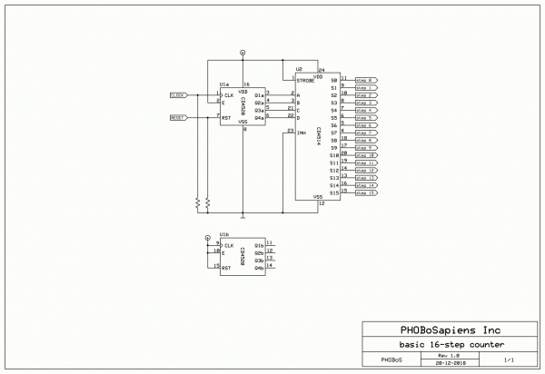
has anyone managed to get a 16 step, cascading 4017 sequencer with selectable number of steps working yet?
I've got the cascading part working fine. Just followed the suggested schematic on the datasheet and paid attention to which of the output are "decoded". It's the number of step that i am having problems with as i see others have had in the past.
Any working approaches to this problem would be very well received.
Cheers
NM |
|
|
Back to top
|
|
|
PHOBoS

Joined: Jan 14, 2010
Posts: 5947
Location: Moon Base
Audio files: 709
|
|
|
Back to top
|
|
|
NuttyMonk
Joined: Jun 30, 2020
Posts: 63
Location: UK
|
| Posted: Tue Sep 29, 2020 4:58 pm Post subject:
|
|
|
Thanks for the quick reply Phobos. I was trying BCD counters and Mux's and then i went onto 4017's but this seems a lot easier to work with then the 4017's. I was hoping there was a 4017 with 16 stages but no such luck.
Will try out some schematic ideas with these two chips instead.
Cheers
NM
p.s. why the resistors to ground on the clock and reset pins? Is this to drain off some of the current going to those pins? |
|
|
Back to top
|
|
|
NuttyMonk
Joined: Jun 30, 2020
Posts: 63
Location: UK
|
| Posted: Tue Sep 29, 2020 5:10 pm Post subject:
|
|
|
| p.s. has anyone ever tried putting a switch and inverter between the bit outs of the counter and the bit ins of the 4514? That should create some different and unusual sequences shouldn't it? |
|
|
Back to top
|
|
|
PHOBoS
Joined: Jan 14, 2010
Posts: 5947
Location: Moon Base
Audio files: 709
|
| Posted: Tue Sep 29, 2020 5:30 pm Post subject:
|
|
|
| NuttyMonk wrote: | | p.s. why the resistors to ground on the clock and reset pins? Is this to drain off some of the current going to those pins? |
That's to keep them from floating if you don't connect anything else directly to them for example if you use them as patch points.
If you do leave pins on CMOS chips unconnected they are sensitive to (electromagnetic) noise and can switch between states
which can cause unwanted behaviour. If however you hardwire them as part of a circuit you don't need them. For some more
info see basic guidelines for digital circuit design.
| Quote: | | p.s. has anyone ever tried putting a switch and inverter between the bit outs of the counter and the bit ins of the 4514? That should create some different and unusual sequences shouldn't it? |
yes, you can get some nice patterns by messing with the bits. Instead of inverters you can use XOR gates which work
as switchable inverters and if you invert all the bits it will count backwards.
_________________
"My perf, it's full of holes!"
http://phobos.000space.com/
SoundCloud BandCamp MixCloud Stickney Synthyards Captain Collider Twitch YouTube
Last edited by PHOBoS on Tue Sep 29, 2020 6:19 pm; edited 1 time in total |
|
|
Back to top
|
|
|
NuttyMonk
Joined: Jun 30, 2020
Posts: 63
Location: UK
|
| Posted: Tue Sep 29, 2020 5:33 pm Post subject:
|
|
|
| Quote: |
yes, you can get some nice patterns by messing with the bits. Instead of inverters you can use XOR gates which work
as switchable inverters and if you invert all the bits it will count backwards. |
Nice. Will have to look into that. And thanks for the CMOS info. Will be useful.
NM |
|
|
Back to top
|
|
|
dk
Joined: Feb 12, 2019
Posts: 115
Location: Europe
|
| Posted: Wed Sep 30, 2020 11:53 am Post subject:
|
|
|
If you do go the 4017 route, the setup in the datasheet posted on the first page of this thread or the stuff PHOBoS posted that he linked to are the way to go... otherwise, I agree with PHOBoS on using a binary counter + binary to decimal decoder. Way simpler, and you often get cool additional features on the binary counter, like the ability to switch directions, preload (skip to any given step, either through a gate input or by pressing a button), etc.
OT, but since I gathered from the other thread you had posted that you like sequencers  , you can replace the sequencer core with a shift register and get a VERY basic version of a Klee sequencer. Perhaps for a future project? , you can replace the sequencer core with a shift register and get a VERY basic version of a Klee sequencer. Perhaps for a future project? 
_________________
Horrors Of Dial-Up! on Facebook
Horrors Of Dial-Up! on Instagram |
|
|
Back to top
|
|
|
blakeAlbion
Joined: Jun 16, 2020
Posts: 25
Location: Boston, Massachusetts, USA
|
| Posted: Thu Apr 28, 2022 8:54 pm Post subject:
|
|
|
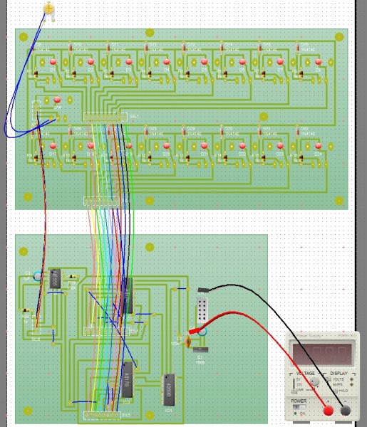
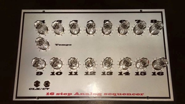
I built my first 4017 sequencer when I was 16 back in 1983. A year later I figured out it was terrible for generating musical pitches but great for generating patterns. A year later I figured out how to use the carry/enable to cascade 2 together to do a 16 step sequencer. With 4 banks of dual 8-switch DIP switches I had a 4-channel drum machine.
I'm looking at a junked Cort CRM-260 Drummer drum machine tonight and I can see the dead 16 pin IC is just a 4017.
I recall buying a MM5871 IC at Radio Shack. I am surprised you can 't buy something like this today. I know Barton makes a 4 channel rhythm chip but for maximum cheese you need enough channels to drive your Latin percussion section. |
|
|
Back to top
|
|
|
PHOBoS
Joined: Jan 14, 2010
Posts: 5947
Location: Moon Base
Audio files: 709
|
| Posted: Thu May 05, 2022 12:27 pm Post subject:
|
|
|
| blakeAlbion wrote: | | I am surprised you can 't buy something like this today. I know Barton makes a 4 channel rhythm chip but for maximum cheese you need enough channels to drive your Latin percussion section. |
Apart from vintage chips it makes sense that they aren't produced anymore. These days it's much easier and cheaper to just use a microcontroller or an FPGA.
I have thought about burning EPROMS to be used as rhythm or pattern chips and make those available (could have 8 channels if you keep it simple), but that
would still require some additional circuitry and again it's easier, not to mention more versatile, to just use a microcontroller. I still love using discrete logic though.
_________________
"My perf, it's full of holes!"
http://phobos.000space.com/
SoundCloud BandCamp MixCloud Stickney Synthyards Captain Collider Twitch YouTube |
|
|
Back to top
|
|
|
rlender90
Joined: Jan 21, 2023
Posts: 3
Location: United States
|
| Posted: Sat Jan 21, 2023 7:41 pm Post subject:
|
|
|
First thread I'm reaching out in, I know it's an older one, but hoping someone can answer my question.
I'm building a 2x4017 16 step sequencer. I'm putting a 12-position rotary switch in, and was wondering, for the common pin to reset the sequence - does that go to pin 15 on both 4017s or just the first? |
|
|
Back to top
|
|
|
PHOBoS
Joined: Jan 14, 2010
Posts: 5947
Location: Moon Base
Audio files: 709
|
| Posted: Sun Jan 22, 2023 1:39 pm Post subject:
|
|
|
 
I don't know which design you are planning to use but with a single 12step rotary switch you will probably be limited to resetting
the second or first 4017 only. Not all is lost though, if you want 16 steps you could hardwire the first 4017 to 7 steps. Then reset
the second one on steps 2/3/4/5/6/7/8/9/10. The stepcount is 1 lower than the step you use to reset so combined with the 7
steps from the first one that would give you the option to switch from 8~16 steps.
_________________
"My perf, it's full of holes!"
http://phobos.000space.com/
SoundCloud BandCamp MixCloud Stickney Synthyards Captain Collider Twitch YouTube |
|
|
Back to top
|
|
|
rlender90
Joined: Jan 21, 2023
Posts: 3
Location: United States
|
| Posted: Sun Jan 22, 2023 4:12 pm Post subject:
|
|
|
| PHOBoS wrote: |
I don't know which design you are planning to use but with a single 12step rotary switch you will probably be limited to resetting
the second or first 4017 only. Not all is lost though, if you want 16 steps you could hardwire the first 4017 to 7 steps. Then reset
the second one on steps 2/3/4/5/6/7/8/9/10. The stepcount is 1 lower than the step you use to reset so combined with the 7
steps from the first one that would give you the option to switch from 8~16 steps. |
If I use a 1p8t and do every other step like run 2/4/6/8/10/12/14/16 to the rotary pot then common to 15 on the first chip would that work? |
|
|
Back to top
|
|
|
PHOBoS
Joined: Jan 14, 2010
Posts: 5947
Location: Moon Base
Audio files: 709
|
| Posted: Wed Feb 08, 2023 12:33 pm Post subject:
|
|
|
| rlender90 wrote: | | If I use a 1p8t and do every other step like run 2/4/6/8/10/12/14/16 to the rotary pot then common to 15 on the first chip would that work? |
right, I was going to reply to this. sorry about that, bad habit 
It depends a bit on the circuit you use but the second chip wouldn't care if you only reset the first one. Either it just keeps counting
or if you use the CLK enable pin it will hold at that step which would result in having two active outputs at the same time (one on each chip).
The 4017 doesn't have a way to turn an output off so the trick that is used is to sort of "park" it at a step that is not used as an output.
Then it will just wait there until it gets a reset pulse and starts counting from the start again while the other chip is "parked".
_________________
"My perf, it's full of holes!"
http://phobos.000space.com/
SoundCloud BandCamp MixCloud Stickney Synthyards Captain Collider Twitch YouTube |
|
|
Back to top
|
|
|
blakeAlbion
Joined: Jun 16, 2020
Posts: 25
Location: Boston, Massachusetts, USA
|
| Posted: Thu Mar 23, 2023 1:55 pm Post subject:
Yuh, 1 4017 split by AND gates. |
|
|
Back in the 80s we used 4 quad AND gate chips, controlled by a 4013 to switch at the start/end of each 8-beat bar.
The a bunch of diodes feeding the outputs into 4 pairs of mini-dips.
So we had a 4-voice 16 step drum machine, programmable by DIP switches.
http://benjamintremblay.com/retro/audio/Narrow_Decade.mp3
There's probably a better way to do this. These days I would use an Arduino Mega or just a bunch of multiplexers with a cheap Arduino-ish board.
The 4017 doesn't really offer you anything you wouldn't get from an Arduino. And if you use Arduino you could use someone's library, like fifteenstep, and hang some sync options off it.
A sequencer based on knobs seems really wonky to me. Very hard to keep in tune. |
|
|
Back to top
|
|
|
|

 Forum index » DIY Hardware and Software » Lunettas - circuits inspired by Stanley Lunetta