| Author |
Message |
JAMESveeder
Joined: Nov 16, 2010
Posts: 34
Location: tucson
|
|
|
Back to top
|
|
 |
andrewF

Joined: Dec 29, 2006
Posts: 1176
Location: australia
Audio files: 4
|
 Posted: Tue Nov 16, 2010 10:30 pm Post subject: Posted: Tue Nov 16, 2010 10:30 pm Post subject:
|
  |
|
Hi
 to e-m to e-m
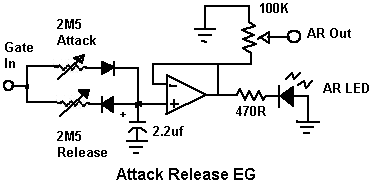
its a good idea to start building with simple circuits, so you are certainly on the right track. The 1st circuit you posted would be hard to control with a voltage source (like the AR EG).
The AR EG needs a gate signal to work, which is a (say) 5V voltage that stays at 5V for as long as you need it to, then it returns to 0V.
The simplest way to achieve this is with a momentary switch wired to +V on one side and to the gate input on the other (via a resistor, say 10k, would be nice)
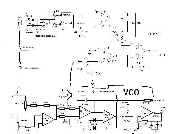
May I suggest you have a look at the circuits designed by Nicolas on this forum. Especially his super-simple VCOs.
They are only slightly more complex than what you are attempting but are quite elegant and work very well. Build a few of them and you have the makings of a very good inexpensive synth.
Have fun
 |
|
|
Back to top
|
|
|
JAMESveeder
Joined: Nov 16, 2010
Posts: 34
Location: tucson
|
| Posted: Tue Nov 16, 2010 10:48 pm Post subject:
|
|
|
Hey, andrewf, thanks for the quick reply! Okay, so the AR EG would be the VC source? I think I may be a little confused.
So would the envelope come "before" the oscillator, controlling the voltage (output level i'm assuming?) with timing via the momentary switch?
I dunno, I feel like I have a good understanding of how a synthesizer works considering my experience with VSTs and VSTi programming, but now that I've moved over into the hardware realm it seems to be much different.
Also I did check out those schematics, looks like there's some great stuff there. Can't wait to get into more complicated, fun builds, as I've created many 555 circuits, but now I'm looking for something more. |
|
|
Back to top
|
|
|
andrewF
Joined: Dec 29, 2006
Posts: 1176
Location: australia
Audio files: 4
|
| Posted: Tue Nov 16, 2010 11:15 pm Post subject:
|
|
|
Usually controlling a VCO with a voltage (such as the output from an EG) means you control the frequency of the VCO (the pitch).
To control the output level (the volume) you need a VCA
So, yes you can use an EG to control a VCO's frequency, the EG can also be used to control the volume when it is routed to a VCA.
To be honest, the momentary switch was only suggested as the most simple means of getting a gate signal, it is useful but its more fun to have simple sequencer or LFO to do the work for you.
you should be familiar with most synth words from VSTs but this glossary might help for any new ones:
http://electro-music.com/forum/topic-18425.html
Also for more simple circuits, check out the Lunetta forum
http://electro-music.com/forum/forum-160.html |
|
|
Back to top
|
|
|
JAMESveeder
Joined: Nov 16, 2010
Posts: 34
Location: tucson
|
| Posted: Tue Nov 16, 2010 11:31 pm Post subject:
|
|
|
Ah of course, I figured I was missing something, so voltage to the VCA would control the output, and of course voltage to the VCO would control the frequency.
So it would go VCO->VCA->Envelope
I did start the baby10 sequencer, started soldering it to a PCB, but I messed up and I've got to get out of my lazy phase and fix it.
But until then I'll probably just use a momentary switch for experimentation. |
|
|
Back to top
|
|
|
JovianPyx

Joined: Nov 20, 2007
Posts: 1988
Location: West Red Spot, Jupiter
Audio files: 224
|
|
|
Back to top
|
|
|
JAMESveeder
Joined: Nov 16, 2010
Posts: 34
Location: tucson
|
| Posted: Wed Nov 17, 2010 5:34 pm Post subject:
|
|
|
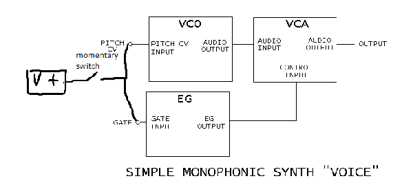
Thanks for the block diagram!
So if I were to have a momentary switch would it look something like this?
i feel like this is wrong, so feedback would be nice
| Description: |
|
| Filesize: |
11.87 KB |
| Viewed: |
5706 Time(s) |

|
| Description: |
|
| Filesize: |
11.87 KB |
| Viewed: |
147 Time(s) |
| This image has been reduced to fit the page. Click on it to enlarge. |
|
Last edited by JAMESveeder on Wed Nov 17, 2010 5:41 pm; edited 1 time in total |
|
|
Back to top
|
|
|
JovianPyx
Joined: Nov 20, 2007
Posts: 1988
Location: West Red Spot, Jupiter
Audio files: 224
|
| Posted: Wed Nov 17, 2010 5:39 pm Post subject:
|
|
|
I can't see the image.
_________________
FPGA, dsPIC and Fatman Synth Stuff
Time flies like a banana.
Fruit flies when you're having fun.
BTW, Do these genes make my ass look fat?
corruptio optimi pessima
|
|
|
Back to top
|
|
|
JAMESveeder
Joined: Nov 16, 2010
Posts: 34
Location: tucson
|
| Posted: Wed Nov 17, 2010 5:41 pm Post subject:
|
|
|
| reattached |
|
|
Back to top
|
|
|
JovianPyx
Joined: Nov 20, 2007
Posts: 1988
Location: West Red Spot, Jupiter
Audio files: 224
|
| Posted: Wed Nov 17, 2010 6:20 pm Post subject:
|
|
|
Well, I'd bet it won't do what you want it to do ... However, build it and see, perhaps I'm wrong.
What I see happening is this - when the switch is closed, the EG is started and the VCO pitch is set to whatever V+ means to it. while the switch remains closed, the EG goes through it's cycle. Once the switch is opened, the VCO pitch will do ??? because with the switch open it really has no input, so the pitch could be anything.
_________________
FPGA, dsPIC and Fatman Synth Stuff
Time flies like a banana.
Fruit flies when you're having fun.
BTW, Do these genes make my ass look fat?
corruptio optimi pessima
|
|
|
Back to top
|
|
|
JAMESveeder
Joined: Nov 16, 2010
Posts: 34
Location: tucson
|
| Posted: Wed Nov 17, 2010 6:29 pm Post subject:
|
|
|
Okay, well this is what my understanding of the circuit is...
The voltage in sets the pitch of the oscillator
I also need voltage fed to the gate in to trigger the envelope which is sent to the VCA controlling the output level.
and just for simple learning purposes i want to use a momentary switch to do this
wouldn't the switch need to be able to send voltage to the oscillator (pretend there is a resistor controlling the voltage to the oscillator after the momentary switch?) and gate in in order to trigger both blocks? |
|
|
Back to top
|
|
|
JovianPyx
Joined: Nov 20, 2007
Posts: 1988
Location: West Red Spot, Jupiter
Audio files: 224
|
| Posted: Wed Nov 17, 2010 6:41 pm Post subject:
|
|
|
What would be more interesting is to vary the pitch independantly from the gate signal. Even something like a pot delivering a voltage to the pitch CV input of the VCO.
_________________
FPGA, dsPIC and Fatman Synth Stuff
Time flies like a banana.
Fruit flies when you're having fun.
BTW, Do these genes make my ass look fat?
corruptio optimi pessima
|
|
|
Back to top
|
|
|
JAMESveeder
Joined: Nov 16, 2010
Posts: 34
Location: tucson
|
| Posted: Wed Nov 17, 2010 7:27 pm Post subject:
|
|
|
| Ah, I see, so I would have constant voltage to the VCO, and use the momentary switch for ONLY the gate, am I right? |
|
|
Back to top
|
|
|
JovianPyx
Joined: Nov 20, 2007
Posts: 1988
Location: West Red Spot, Jupiter
Audio files: 224
|
| Posted: Thu Nov 18, 2010 5:59 am Post subject:
|
|
|
Yes, but the VCO pitch CV doesn't have to remain constant. If you supply that voltage using a pot, if you change the pot while GATE is on, then the pitch will change.
_________________
FPGA, dsPIC and Fatman Synth Stuff
Time flies like a banana.
Fruit flies when you're having fun.
BTW, Do these genes make my ass look fat?
corruptio optimi pessima
|
|
|
Back to top
|
|
|
JAMESveeder
Joined: Nov 16, 2010
Posts: 34
Location: tucson
|
|
|
Back to top
|
|
|
JovianPyx
Joined: Nov 20, 2007
Posts: 1988
Location: West Red Spot, Jupiter
Audio files: 224
|
| Posted: Thu Nov 18, 2010 10:16 am Post subject:
|
|
|
The GATE is a voltage, but sort of special. It's either on or off. It is considered more of a logic signal than anything else and often it's input range is confined. Many systems use 5 volt gate, others use 10 or even 15 volts. However, as I stated, it is an "on or off" signal, meaning that the voltage is either "high" or it should be zero. "high" being what the circuit expects for gate - if it expects 5 volts, then use no more than 5.
For this example, let's assume the GATE needs to be 5 volts for "on" and zero volts for "off".
The diagram below is an example of how this is achieved with a switch. When the switch is OPEN, GATE is _ON_. When the switch is CLOSED, GATE is _OFF_
| Description: |
| Simple Gate Switch Circuit |
|
| Filesize: |
1.36 KB |
| Viewed: |
6909 Time(s) |

|
_________________
FPGA, dsPIC and Fatman Synth Stuff
Time flies like a banana.
Fruit flies when you're having fun.
BTW, Do these genes make my ass look fat?
corruptio optimi pessima
|
|
|
Back to top
|
|
|
JAMESveeder
Joined: Nov 16, 2010
Posts: 34
Location: tucson
|
| Posted: Thu Nov 18, 2010 1:10 pm Post subject:
|
|
|
Okay, that's really simple!
Well I think I'm ready to start this build... time to start buying some parts.
Thanks a LOT for your help, I appreciate it.
I'll finish soldering my baby10 for this one. |
|
|
Back to top
|
|
|
|

 Forum index » DIY Hardware and Software