| Author |
Message |
Cynosure
Site Admin

Joined: Dec 11, 2010
Posts: 1026
Location: Toronto, Ontario - Canada
Audio files: 82
|
 Posted: Sun Feb 24, 2013 7:13 pm Post subject:
Lunetta Reverb Circuit Posted: Sun Feb 24, 2013 7:13 pm Post subject:
Lunetta Reverb Circuit
Subject description: 4006 Digital Delay |
  |
|
I had this idea for a while, but just got around to testing it out tonight. I used two 4006 shift registers to create a digital delay line. It works well with lunetta devices because it can only output square waves, but you can try it with other sound sources if you want. It might sound a little odd though - like the delay is being overdriven.
The attached sound demo starts with just the source waveform, and then I turn up the level of the reverb. Then I play with the pitch of the source. Lastly, I adjust the rate of the delay.
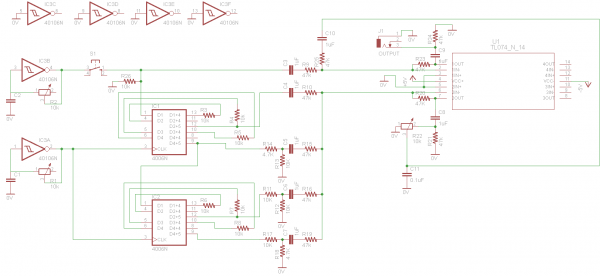
Here is the basic run-down of how it works.
A clock drives two 4006 shift registers. The rate of the clock is essentially the delay rate, but at the same time it is also the sample rate so things can sound a little odd at times.
The shift registers are all set up in series so the output of one goes to the input of the next. This creates a long delay line that spans 36 steps across the two chips.
The input of the first shift register is the sound source input. In my schematic, it is a 40106 oscillator with a momentary switch. That can be replaced with any sound source that goes above the chip's input threshold. Note the need for a pull-down resistor at the input.
I then tap the shift register outputs at four different points. The earliest point has no divider, and the rest have an increased voltage division as they go down the register chain. This makes the first tap point the loudest, and the last tap point the quietest.
All four tap points are mixed with a TL074.
The mixed delayed sounds are sent through a voltage divider volume pot and mixed with the source sound. Adjust the pot controls the level of the reverb.
I also added a 0.1uF cap to ground after the level pot to remove some of the harshness in the reverb sound. This is entirely optional. I like my reverb a little bit warm. I found it makes it sound more like it passed through an actual space, and masks the fact that it is just a repeating square wave of decreasing volume.
THINGS TO TRY
1. Use a complex sound source.
2. More or less tap points.
3. Add more 4006 shift registers to the chain for really long delay time.
4. Increase the clock rate so the sample rate also improves (requires more shift register steps).
5. Try another shift register with more steps.
6. Try filtering the reverb different ways.
| Description: |
|
| Filesize: |
24.69 KB |
| Viewed: |
1259 Time(s) |
| This image has been reduced to fit the page. Click on it to enlarge. |
|
| Description: |
|

Download (listen) |
| Filename: |
4006delay.mp3 |
| Filesize: |
4.87 MB |
| Downloaded: |
1816 Time(s) |
_________________
JacobWatters.com |
|
|
Back to top
|
|
 |
tony void

Joined: Apr 26, 2011
Posts: 40
Location: Parma, Ohio
|
| Posted: Sun Feb 24, 2013 7:37 pm Post subject:
|
|
|
| Awesome! I've wondered about this idea before but didn't think it would work. This opens up so many possibilities. |
|
|
Back to top
|
|
|
RingMad

Joined: Jan 15, 2011
Posts: 430
Location: Montreal, Canada
Audio files: 4
|
| Posted: Mon Feb 25, 2013 12:56 pm Post subject:
|
|
|
Hmnmm, interesting... Alas, the 4006 is out of production I believe, and getting harder to find for some. But what about the 4031, which is a 64-bit shift register?
Anyway, I'll have to check this out one day... too much stuff on the breadboards and waiting for enclosures.
James. |
|
|
Back to top
|
|
|
elmegil

Joined: Mar 20, 2012
Posts: 2179
Location: Chicago
Audio files: 16
|
| Posted: Mon Feb 25, 2013 4:03 pm Post subject:
|
|
|
| 4015 is a dual 4 bit register. I bet 2 or 3 of them could be subbed with the same use. Max clock is only 8MHz, but I don't see that as a drawback.... |
|
|
Back to top
|
|
|
Cynosure
Site Admin
Joined: Dec 11, 2010
Posts: 1026
Location: Toronto, Ontario - Canada
Audio files: 82
|
| Posted: Mon Feb 25, 2013 5:13 pm Post subject:
|
|
|
| RingMad wrote: | | But what about the 4031, which is a 64-bit shift register? |
Even better! That will give you twice the delay length with only one chip. A longer delay length will mean that you can clock it faster and won't get sample rate issues with higher frequencies.
| elmegil wrote: | | Max clock is only 8MHz, but I don't see that as a drawback.... |
I was nowhere near 8MHz clock speed. I don't have enough steps to have an audible delay with a high frequency clock. Another reason why the 4031 sounds like a good choice.
_________________
JacobWatters.com |
|
|
Back to top
|
|
|
analog_backlash

Joined: Sep 04, 2012
Posts: 393
Location: Aldershot, UK
Audio files: 21
|
| Posted: Mon Feb 25, 2013 5:32 pm Post subject:
|
|
|
This is brilliant! Another circuit to add to my impossible list of circuits to try before I die (circuit bucket list?).
| tony void wrote: | | Awesome! I've wondered about this idea before but didn't think it would work. This opens up so many possibilities. |
I had also thought that this should be possible, but I was too stupid to work it out 
Gary |
|
|
Back to top
|
|
|
PHOBoS

Joined: Jan 14, 2010
Posts: 5935
Location: Moon Base
Audio files: 709
|
|
|
Back to top
|
|
|
Cynosure
Site Admin
Joined: Dec 11, 2010
Posts: 1026
Location: Toronto, Ontario - Canada
Audio files: 82
|
| Posted: Mon Feb 25, 2013 6:48 pm Post subject:
|
|
|
Thanks phobos! <3
James - replace the 4006 ic's with one 4031 and crank up the clock rate 
_________________
JacobWatters.com
Last edited by Cynosure on Mon Feb 25, 2013 8:27 pm; edited 1 time in total |
|
|
Back to top
|
|
|
PHOBoS
Joined: Jan 14, 2010
Posts: 5935
Location: Moon Base
Audio files: 709
|
|
|
Back to top
|
|
|
LeftyLogic

Joined: Feb 09, 2013
Posts: 9
Location: Paola, KS
|
| Posted: Mon Feb 25, 2013 7:27 pm Post subject:
|
|
|
After seeing this thread and wondering, "What's a shift register?" I did some reading and it sounds like you could do some really fun things to this circuit with a 4031 chip; it has two inputs that it switches between depending on whether the voltage at the switch pin is high or low, so I bet you could put a toggle switch on that pin, hook up your oscillator to input 1, and then feed the output back into input two for some endless looping fun!
Or, for extra weirdness you could get rid of the toggle switch entirely, divide the input signal down into the LFO range and hook THAT up to the switch pin!
Although I have to admit, I'm seriously new to this whole SDIY/Lunetta stuff so I wouldn't be surprised if none of this works, but hey, it was fun to research |
|
|
Back to top
|
|
|
kkissinger
Stream Operator

Joined: Mar 28, 2006
Posts: 1472
Location: Kansas City, Mo USA
Audio files: 45
|
| Posted: Mon Feb 25, 2013 7:41 pm Post subject:
|
|
|
Brilliant idea! You could feed two such delays and have a stereophonic lunetta.
_________________
-- Kevin
http://kevinkissinger.com |
|
|
Back to top
|
|
|
corex

Joined: Mar 02, 2010
Posts: 114
Location: Las Vegas
|
| Posted: Tue Feb 26, 2013 2:07 pm Post subject:
|
|
|
| Using a shift register like a BBD is clever. Good idea! |
|
|
Back to top
|
|
|
bingmachine
Joined: Jan 23, 2009
Posts: 19
Location: Sweden
|
| Posted: Thu Mar 07, 2013 3:06 pm Post subject:
|
|
|
| I just saw the datasheet of the 40105. It's essentially 4 16-bit shift-registers, with common clock - and then some more. It should be ideal for this application, shouldn't it? |
|
|
Back to top
|
|
|
|

 Forum index » DIY Hardware and Software » Lunettas - circuits inspired by Stanley Lunetta