| Author |
Message |
synaesthesia

Joined: May 27, 2014
Posts: 291
Location: Germany
Audio files: 85
|
 Posted: Sat Nov 15, 2014 1:22 pm Post subject:
Fun with the 4046 PLL Posted: Sat Nov 15, 2014 1:22 pm Post subject:
Fun with the 4046 PLL
Subject description: circuit snippets that sound interesting |
  |
|
The 4046 PLL is a chip that I haven't used before. So I finally sat down and played with it a bit. So far I am using only the VCO part, which works just great.
The first snippet is meant to emphasize the interference sound that you get from mixing two close frequencies. However, in the INTERFERENCER circuit, I am feeding the VCO not with one voltage, but with a fast triangle wave from a first shift register. The resulting frequency from the 4046 is then divided down by a second shift register. When tuning the triangle wave frequency against the VCO range, you get many places where a nice interference can be heard. Listen for yourself. In the first half of the recording I am only changing the triangle wave frequency. In the second half I am only changing the 4046 VCO range.
| Description: |
|
| Filesize: |
34.53 KB |
| Viewed: |
1935 Time(s) |
| This image has been reduced to fit the page. Click on it to enlarge. |
|
| Description: |
|

Download (listen) |
| Filename: |
Interferencer.mp3 |
| Filesize: |
1.96 MB |
| Downloaded: |
2899 Time(s) |
Last edited by synaesthesia on Sat Nov 15, 2014 2:59 pm; edited 3 times in total |
|
|
Back to top
|
|
 |
synaesthesia
Joined: May 27, 2014
Posts: 291
Location: Germany
Audio files: 85
|
| Posted: Sat Nov 15, 2014 1:24 pm Post subject:
|
|
|
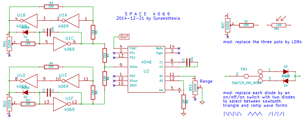
In the second circuit snippet I am feeding the 4046 with a mix of a fast ramp wave and a slow ramp wave. The ramps are generated by a counter with a resistor network at the outputs. Of course this is not a clean ramp, but actually a stepped wave form. You could add a 4.7uF condensator from RV3 pin 3 to ground to smooth the slower ramp a bit. A pot is used to mix the two wave forms and then send the result to the 4046 VCO input. In the recording I am changing all four pots, but only one at a time. You can get an idea of the many interesting sounds created by the SPACE4046 circuit below from the recording.
| Description: |
|
| Filesize: |
35.74 KB |
| Viewed: |
1794 Time(s) |
| This image has been reduced to fit the page. Click on it to enlarge. |

|
| Description: |
|
Download (listen) |
| Filename: |
Space4046.mp3 |
| Filesize: |
2.81 MB |
| Downloaded: |
2916 Time(s) |
|
|
|
Back to top
|
|
|
elmegil

Joined: Mar 20, 2012
Posts: 2179
Location: Chicago
Audio files: 16
|
| Posted: Sat Nov 15, 2014 4:24 pm Post subject:
|
|
|
nice sounds....  |
|
|
Back to top
|
|
|
commathe

Joined: Jul 26, 2013
Posts: 153
Location: Beijing
Audio files: 5
|
| Posted: Sun Nov 16, 2014 1:13 am Post subject:
|
|
|
| Really interesting stuff! Its making me put a 4046 module much higher on my build list. |
|
|
Back to top
|
|
|
RingMad

Joined: Jan 15, 2011
Posts: 430
Location: Montreal, Canada
Audio files: 4
|
| Posted: Sun Nov 16, 2014 10:39 am Post subject:
|
|
|
I've used the basic 4046 VCO many times, but never with this kind of inputs... there are some very interesting sounds you're making. Thanks for sharing.
James. |
|
|
Back to top
|
|
|
PHOBoS

Joined: Jan 14, 2010
Posts: 5980
Location: Moon Base
Audio files: 709
|
|
|
Back to top
|
|
|
PHOBoS
Joined: Jan 14, 2010
Posts: 5980
Location: Moon Base
Audio files: 709
|
|
|
Back to top
|
|
|
PHOBoS
Joined: Jan 14, 2010
Posts: 5980
Location: Moon Base
Audio files: 709
|
| Posted: Sun Nov 16, 2014 8:22 pm Post subject:
SPACE4046 test |
|
|
I did a test with the SPACE4046
I used a VCO for the fast ramp wave which itself was modulated with a slow ramp wave (counter + R2R).
I also used the 4046 XOR as ringmod (as explained above) together with another squarewave oscillator.
I used the ramp output of another 4046 VCO for a drone, which was modulated by the LFO that was controllling
the counter for the fast ramp wave VCO and I added some delay 
I like this SPACE4046 thing! 
(another mod could be XOR's between the outputs of the 4520 and the resistors so you can change the direction)
audio posted here
_________________
"My perf, it's full of holes!"
http://phobos.000space.com/
SoundCloud BandCamp MixCloud Stickney Synthyards Captain Collider Twitch YouTube |
|
|
Back to top
|
|
|
blue hell
Site Admin

Joined: Apr 03, 2004
Posts: 24676
Location: The Netherlands, Enschede
Audio files: 330
G2 patch files: 320
|
| Posted: Tue Nov 18, 2014 9:58 am Post subject:
|
|
|
Ah .. here it the source of the PHOBoS track .. nice circuits!
_________________
Jan
also .. could someone please turn down the thermostat a bit.

9 3 4 .. erm .. not 13 then? .. hmm, ah eight! .. yeah yeah as in 8647 .. 47 is an 88 .. pwew .. numbles! |
|
|
Back to top
|
|
|
PHOBoS
Joined: Jan 14, 2010
Posts: 5980
Location: Moon Base
Audio files: 709
|
|
|
Back to top
|
|
|
synaesthesia
Joined: May 27, 2014
Posts: 291
Location: Germany
Audio files: 85
|
|
|
Back to top
|
|
|
DUBmatze

Joined: Feb 18, 2013
Posts: 150
Location: south Germaica (schwabilon)
|
| Posted: Thu Nov 20, 2014 1:04 pm Post subject:
|
|
|
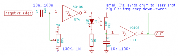
| synaesthesia wrote: | | it sounds great and you get something close to a synth drum sound. The circuit below can also be used stand-alone. The sound is generated entirely during the recovery period of the LDR after it has been lit by the LED with a brief flash. It it surprising how slow these LDRs are. Use an LDR with a high dark resistance. Only drawback is that it keeps going a while even at a very low frequency, which results in audible clicks. Could be gated with the trigger maybe, but I didn't follow-up on this yet. |
thats the way i build my lickshoters:
(this is a singing Squrewave alongside with one of my lickshot circuits)
you can avoid the sound keeps going with a big pulldown resistor (cant rember, and dont have anything here to check) but i think it was somthing like 1m-10m to the input or output of the osc(gate). A enclosure will also help. (the most unneedet light come from the back of the LED in it.) |
|
|
Back to top
|
|
|
synaesthesia
Joined: May 27, 2014
Posts: 291
Location: Germany
Audio files: 85
|
| Posted: Thu Nov 20, 2014 1:31 pm Post subject:
|
|
|
Ahh, cool. I just found your LickShot schematic by clicking on the icon next to your recording on SoundCloud. I like your idea to use a pot to balance between two different (I guess) caps.
Seems the pull-down resistor was 1M at the input of the inverter. Yep, the enclosure is very important. I used two layers of heat-shrink tube actually to make it lightproof. |
|
|
Back to top
|
|
|
DUBmatze
Joined: Feb 18, 2013
Posts: 150
Location: south Germaica (schwabilon)
|
| Posted: Thu Nov 20, 2014 5:04 pm Post subject:
|
|
|
| synaesthesia wrote: | | I like your idea to use a pot to balance between two different (I guess) caps |
shure diffrent caps. this must be a verry small pot (10k or smaller). a cool tone controll for this is also when u use 3 different caps. Somthing like: a 10k Pot. on the left taper a mini cap on the right side a big cap. and the middel connect a resistor followed by a medium cap. this will make a pitch controll for the LDR osc. To change the "envelope" you can shrink more than one LED in. i figured out the ldrs i had (cheap china bulk buy, so no datashet...) are most sensitiv to green light. so i add a 2nd pot to fade between a green and a red LED. this need some tweaking (in my case the red one must be brighter) i think this only will work with extrem "slow" LDRs...
i also played a bit arround with dif. LFOs for the green and the red LEDs. you get some kind of "modulation" from the red one.
Realy cool is when you tigger with one LED two (LDR)osc and NAND mix that together. (this sound: http://youtu.be/ja1cw30o-YE ) |
|
|
Back to top
|
|
|
synaesthesia
Joined: May 27, 2014
Posts: 291
Location: Germany
Audio files: 85
|
| Posted: Sat Nov 22, 2014 8:15 am Post subject:
|
|
|
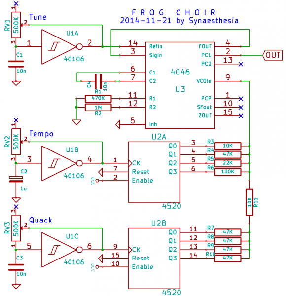
Here is a circuit snippet that sometimes sounds a bit like a frog choir. A slow counter with a resistor network generates a sequence of voltages that are fed into a 4046 VCO to produce a tune. The XOR from the 4046 PLL is used for ring modulation of that melody. When a stepped triangle wave from a second counter is mixed to the control voltage, a kind of resonance is added to the tune. The slower the triangle wave, the more "resonance" it generates. I called it "Quack" in the schematic.
An interesting effect can be heard when the ring modulation frequency is changed: it appears that the tune is actually changing. My guess is that this happens when the frequency of a specific tone matches the ring modulation frequency, which doubles the resulting tone frequency.
In the recording I start with a slow tune without "quack", then accelerating and increasing the ring modulation frequency. You can hear the tune changing a bit during that. After the middle part, I increase the amount of "quack" to maximum and then start decreasing the ring modulation frequency, which again changes the tune at a few points.
| Description: |
|
| Filesize: |
36.81 KB |
| Viewed: |
1161 Time(s) |
| This image has been reduced to fit the page. Click on it to enlarge. |
|
| Description: |
|
Download (listen) |
| Filename: |
FrogChoir.mp3 |
| Filesize: |
1.96 MB |
| Downloaded: |
2077 Time(s) |
|
|
|
Back to top
|
|
|
synaesthesia
Joined: May 27, 2014
Posts: 291
Location: Germany
Audio files: 85
|
|
|
Back to top
|
|
|
synaesthesia
Joined: May 27, 2014
Posts: 291
Location: Germany
Audio files: 85
|
| Posted: Fri Feb 13, 2015 4:09 pm Post subject:
|
|
|
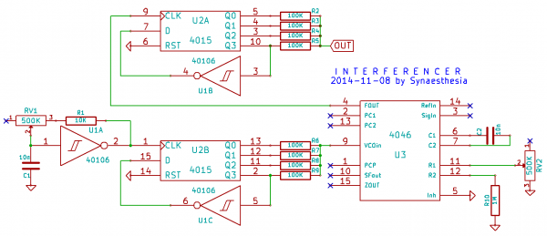
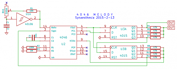
Here is a little circuit that generates a random melody using a 4046 and a 4015 shift register. The shift register output is run through the XOR gate from the 4046. Depending on the current state of the slow oscillator (a simple 40106 circuit here, anything else will work as well) the result is fed back into the shift register either inverted or unchanged. The random state of the shift register pattern determines the tone that is sent to the output via an optional resistor network as well as the control voltage that is sent to the 4046. The VCO output frequency is then used to clock the shift register. The self-modulating feedback generates a pretty random sequence of tones as you can hear in the recording.
| Description: |
|
| Filesize: |
29.82 KB |
| Viewed: |
1072 Time(s) |
| This image has been reduced to fit the page. Click on it to enlarge. |
|
| Description: |
|
Download (listen) |
| Filename: |
4046Melody.mp3 |
| Filesize: |
1.15 MB |
| Downloaded: |
1919 Time(s) |
Last edited by synaesthesia on Sun Mar 15, 2015 3:29 pm; edited 1 time in total |
|
|
Back to top
|
|
|
RingMad
Joined: Jan 15, 2011
Posts: 430
Location: Montreal, Canada
Audio files: 4
|
| Posted: Sat Feb 14, 2015 6:38 am Post subject:
|
|
|
Nice! It's random, but not too much, so it still retains some musicality.
.: James :. |
|
|
Back to top
|
|
|
synaesthesia
Joined: May 27, 2014
Posts: 291
Location: Germany
Audio files: 85
|
| Posted: Tue Apr 07, 2015 11:54 am Post subject:
|
|
|
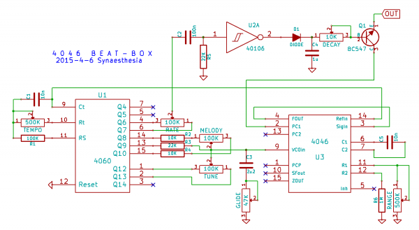
Here is a little snippet that turns a 4046 and a counter into a simple beat-box. I have originally used a 4040 counter in my test, but a 4060 may be used as well and saves an extra oscillator. You might have to experiment with Rt and Ct for the 4046 a bit. The 4060 counter is used for the tempo only, so the frequency is not too critical.
The low frequency counter outputs are mixed via a resistor network for the VCO input. The "melody" is generated by R2, R3, R4 and the 100K pot. The ratio of these resistor values should not change to give the best range of waveforms to drive the 4046 VCO. I have added two extra outputs from the counter plus a pot on top to vary the waveforms even a bit more, this is optional. The rate pot is used to select between two counter outputs for the envelope generator. There is no smooth transition but a sudden change, so it could be replaced by a switch.
The 4046 provides the VCO plus the extra XOR that is used to give the sound a metallic timbre. A glide pot can be used to vary the transitions between the beats (Edit: 22K is sufficient). The range pot at the 4046 controls the VCO range and may be used to shift the generated sounds towards a higher frequency range. Edit: Pin 5 (INH) should go to ground of course.
The 40106 inverter plus transistor is part of a VCA to provide an envelope. The circuit should even work without the extra inverter if you increase C2 to 1 or 2.2 uF. The decay pot modifies the sounds between short percussive beats and longer tones (Edit: better use 47K). The transistor is not critical, any NPN type should work.
During the recording I changed the setting of each pot to demonstrate the full range of sounds. At 1:22 I adjusted the rate pot to increase the tempo.
| Description: |
|
| Filesize: |
39.98 KB |
| Viewed: |
2096 Time(s) |
| This image has been reduced to fit the page. Click on it to enlarge. |
|
| Description: |
|
Download (listen) |
| Filename: |
4046 Beat-Box.mp3 |
| Filesize: |
3.73 MB |
| Downloaded: |
2193 Time(s) |
Last edited by synaesthesia on Wed Apr 08, 2015 11:22 am; edited 1 time in total |
|
|
Back to top
|
|
|
RingMad
Joined: Jan 15, 2011
Posts: 430
Location: Montreal, Canada
Audio files: 4
|
| Posted: Wed Apr 08, 2015 6:13 am Post subject:
|
|
|
Cool circuit! Thanks for sharing.
.: James :. |
|
|
Back to top
|
|
|
rico C
Joined: Feb 27, 2014
Posts: 26
Location: Redondo Beach
|
| Posted: Sun Apr 12, 2015 11:27 am Post subject:
|
|
|
| great stuff |
|
|
Back to top
|
|
|
synaesthesia
Joined: May 27, 2014
Posts: 291
Location: Germany
Audio files: 85
|
| Posted: Fri Sep 11, 2015 3:49 pm Post subject:
|
|
|
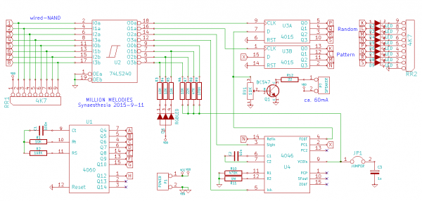
Here is one more fun circuit with the 4046. I wanted to build something loosely based on the pattern generator I am experimenting with. Instead of the simplistic oscillator that I have used there, I am using a 4046 this time because it sounds so much better. The melodies should be generated from a pattern generator core based on shift registers. I have used the XOR from the 4046 together with one 4015 shift register as the basis for that. The other shift register is wired as random bit generator by feeding the output from the VCO into the data input. Finally, a 4060 is used to provide the basic clock frequencies to drive the clock inputs. The resistor network R3-R6 generates the control voltage for the 4046 VCO, which will result in 16 possible tones.
When running the circuit, any output from the counter (A to H) and shift registers (K to N and P to S) may be connected to any of the eight inputs (a to h). Overall, there will be over 400 million possibilities to connect all eight inputs. For that I plan to use a 12 by 16 field of female pin headers. For each input I present only 12 outputs instead of the 16 available, leaving out those that do not makes sense, for example, feeding a shift register output back to the clock input of the same shift register. The connections will be made with LEDs, so that you can see the selected bit stream while the melody is being generated. With a power supply of 5V and 4K7 pull-up resistors the voltage drop at the LEDs is barely big enough to provide a valid LOW signal and thus I added eight Schmitt-Trigger inverters from a 74HC240 to the inputs. This should work better at higher supply voltages.
I still have to solder this circuit to see the effect of the blinking LEDs when patching a melody. However, I have patched it in my Lunetta-Lab and created a short recording with a few samples of the melodies this circuit can generate. There is just the right amount of regular pattern and randomness that I was looking for.
| Description: |
|
| Filesize: |
34.52 KB |
| Viewed: |
972 Time(s) |
| This image has been reduced to fit the page. Click on it to enlarge. |

|
| Description: |
|
Download (listen) |
| Filename: |
MillionMelodies.mp3 |
| Filesize: |
992.76 KB |
| Downloaded: |
1716 Time(s) |
|
|
|
Back to top
|
|
|
trav

Joined: Sep 11, 2012
Posts: 108
Location: Auckland
Audio files: 16
|
| Posted: Fri Sep 11, 2015 5:02 pm Post subject:
|
|
|
I like the idea with the LEDs; you'll have to post a video.
The bit at the end of the recording is what I next want to look at implementing in a circuit: single voice "chords" a la those old school tracker arpeggio sounds |
|
|
Back to top
|
|
|
Steveg

Joined: Apr 23, 2015
Posts: 184
Location: Perth, Australia
|
| Posted: Mon Sep 14, 2015 7:53 am Post subject:
|
|
|
So many fun circuits. Thanks synaesthesia.  |
|
|
Back to top
|
|
|
synaesthesia
Joined: May 27, 2014
Posts: 291
Location: Germany
Audio files: 85
|
| Posted: Mon Sep 21, 2015 12:18 pm Post subject:
|
|
|
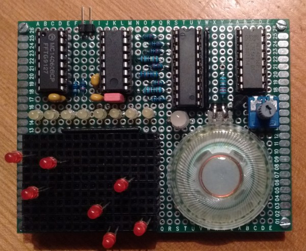
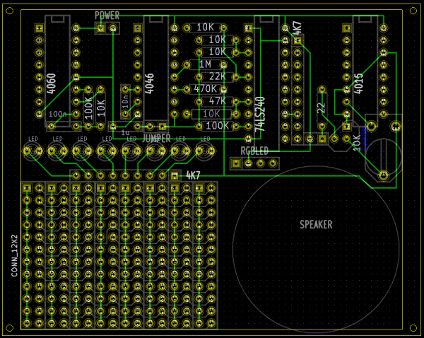
The board is complete and works. I have attached the final schematic and layout as well.
The size of the board is only 7x9 centimeters, but still enough space to have a simple amplifier and speaker on it as well. Because the 4046 generates a simple square wave, a single transistor stage was good enough. I am running at 5V and so far I haven't seen any issues with the logic levels limited by using LEDs for patching.
One part of the board was really ugly to solder. The patch matrix for the LEDs seemed to be a good idea, but the soldering was hell. In the detail you can see the vertical column wires for the inputs made from 0.2mm wire and the horizontal signal wires made from 0.1mm enameled wire. I don't think that I will do that again!
One issue I found with the headers that I was using is that the LEDs only fit well in one direction. Of course I noticed that after I started to solder 8 strips of 12x2 holes and had to remove them to replace them by 6 strips of 16x2 holes.
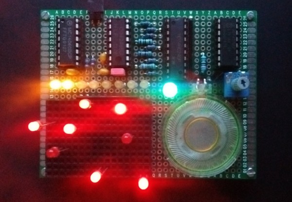
As you can see, I have added a RGB LED as well for extra light-show. Have a look at the movie coming soon!
| Description: |
|
| Filesize: |
45.63 KB |
| Viewed: |
1060 Time(s) |
| This image has been reduced to fit the page. Click on it to enlarge. |
|
| Description: |
|
| Filesize: |
405.78 KB |
| Viewed: |
793 Time(s) |
| This image has been reduced to fit the page. Click on it to enlarge. |
|
| Description: |
|
| Filesize: |
114.92 KB |
| Viewed: |
739 Time(s) |
| This image has been reduced to fit the page. Click on it to enlarge. |
|
| Description: |
|
| Filesize: |
484.28 KB |
| Viewed: |
741 Time(s) |
| This image has been reduced to fit the page. Click on it to enlarge. |

|
| Description: |
|
| Filesize: |
270.5 KB |
| Viewed: |
713 Time(s) |
| This image has been reduced to fit the page. Click on it to enlarge. |
|
|
|
|
Back to top
|
|
|
|

 Forum index » DIY Hardware and Software » Lunettas - circuits inspired by Stanley Lunetta