| Author |
Message |
Estebandito
Joined: Dec 25, 2017
Posts: 33
Location: Amsterdam
Audio files: 3
|
 Posted: Tue Apr 26, 2022 12:38 pm Post subject:
Automated voltage divider thingy Posted: Tue Apr 26, 2022 12:38 pm Post subject:
Automated voltage divider thingy
Subject description: something I’m wiggling on |
  |
|
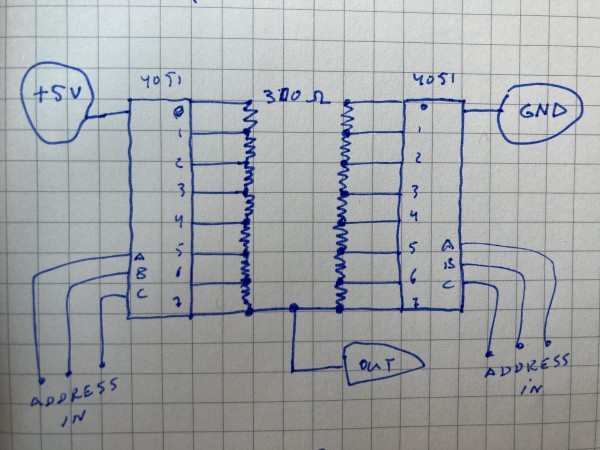
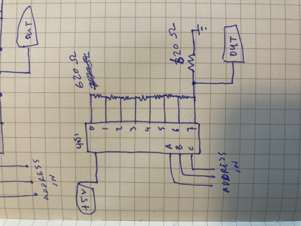
Hey everyone, just before leaving the studio today I threw together this thing on the breadboard. It’s a simple idea for an automated voltage divider. I put it together as a starting point for my next studio session and I haven’t actually tried using it yet. Looks like I need to amp the output before it is at all useable, or use smaller resistances? what do you think? I think I will try using this double mux thing in an oscillator as well.
| Description: |
|
| Filesize: |
4.43 MB |
| Viewed: |
260 Time(s) |
| This image has been reduced to fit the page. Click on it to enlarge. |
|
| Description: |
|
| Filesize: |
3.86 MB |
| Viewed: |
258 Time(s) |
| This image has been reduced to fit the page. Click on it to enlarge. |
|
| Description: |
|

Download (listen) |
| Filename: |
trim.9EE4EBE9-0D67-40B1-AF57-53043EA6354B.MOV |
| Filesize: |
9.54 MB |
| Downloaded: |
384 Time(s) |
|
|
|
Back to top
|
|
 |
PHOBoS

Joined: Jan 14, 2010
Posts: 5980
Location: Moon Base
Audio files: 709
|
Posted: Tue Apr 26, 2022 5:57 pm Post subject:
Re: Automated voltage divider thingy
Subject description: something I’m wiggling on |
|
|
| Estebandito wrote: | | Hey everyone, just before leaving the studio today I threw together this thing on the breadboard. It’s a simple idea for an automated voltage divider. I put it together as a starting point for my next studio session and I haven’t actually tried using it yet. Looks like I need to amp the output before it is at all useable, or use smaller resistances? what do you think? I think I will try using this double mux thing in an oscillator as well. |
A couple of notes if you want to use it as drawn,. so connected between GND and +5V.
If you set both muxes to address 111 you are basically creating a direct short through the 2 chips which they probably won't be too happy with.
Also at the moment you have 6-bits as an input which in theory could give you 64 different voltages but in this configuration there are some
duplicates, for example if the address is the same for both muxes. (assuming all the resistors have the same value). This isn't necessarily a bad
thing though and honestly I am kinda curious what the levels and distribution of those would be.
I am actually currently working on a circuit that is half of that (1 mux + resistors) to use as a DAC, though it's wired up a bit differently.
That first circuit you drew is basically a DAC, be it a bit of an odd one. I do like how you approached this and how each mux is one half
of a voltage divider but adjustable, so it is like having 2 potentiometers in series. Could be interesting depending on how you control it.
I guess you could do a similar thing with 2 R2R resistor ladders.
_________________
"My perf, it's full of holes!"
http://phobos.000space.com/
SoundCloud BandCamp MixCloud Stickney Synthyards Captain Collider Twitch YouTube |
|
|
Back to top
|
|
|
Estebandito
Joined: Dec 25, 2017
Posts: 33
Location: Amsterdam
Audio files: 3
|
| Posted: Wed Apr 27, 2022 12:21 am Post subject:
|
|
|
| Quote: | | If you set both muxes to address 111 you are basically creating a direct short through the 2 chips which they probably won't be too happy with. |
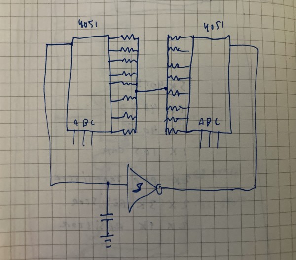
You’re right. I could add a resistor to the +5v input, but wiring the chips up differently and using all different resistors is actually more interesting because I’d more easily avoid the duplicates.
One of the things I want to use this for is to drive a vactrol.
I am expecting the 4069 to work to beef up the output level, otherwise a 358?
| Description: |
|
| Filesize: |
2.89 MB |
| Viewed: |
251 Time(s) |
| This image has been reduced to fit the page. Click on it to enlarge. |
|
| Description: |
| This is a version I didn’t test but I assume it works, and this is probably similar to the design you mention you are working on? |
|
| Filesize: |
3.24 MB |
| Viewed: |
257 Time(s) |
| This image has been reduced to fit the page. Click on it to enlarge. |
|
|
|
|
Back to top
|
|
|
PHOBoS
Joined: Jan 14, 2010
Posts: 5980
Location: Moon Base
Audio files: 709
|
|
|
Back to top
|
|
|
PHOBoS
Joined: Jan 14, 2010
Posts: 5980
Location: Moon Base
Audio files: 709
|
Posted: Wed Apr 27, 2022 12:35 pm Post subject:
Re: Automated voltage divider thingy
Subject description: something I’m wiggling on |
|
|
| PHOBoS wrote: | | I am kinda curious what the levels and distribution of those would be. |
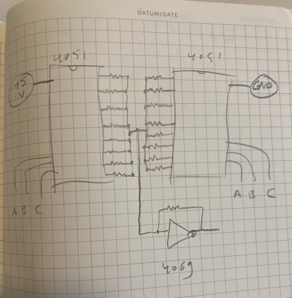
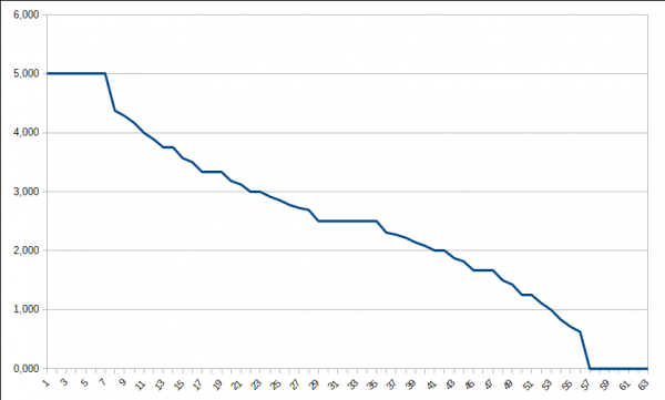
I couldn't resist so here's the list of voltages assuming all resistors have the same value and the muxes don't have any internal resistance.
5.000, 5.000, 5.000, 5.000, 5.000, 5.000, 5.000
4.375
4.286
4.167
4.000
3.889
3.750, 3.750
3.571
3.500
3.333, 3.333, 3.333
3.182
3.125
3.000, 3.000
2.917
2.857
2.778
2.727
2.692
2.500, 2.500, 2.500, 2.500, 2.500, 2.500, 2.500
2.308
2.273
2.222
2.143
2.083
2.000, 2.000
1.875
1.818
1.667, 1.667, 1.667
1.500
1.429
1.250, 1.250
1.111
1.000
0.833
0.714
0.625
0.000, 0.000, 0.000, 0.000, 0.000, 0.000, 0.000
which gives you 37 unique values.
it might be interesting to control one or both of the muxes at audio rates and us it as a waveform generator.
| Description: |
|
| Filesize: |
18 KB |
| Viewed: |
254 Time(s) |
| This image has been reduced to fit the page. Click on it to enlarge. |
|
_________________
"My perf, it's full of holes!"
http://phobos.000space.com/
SoundCloud BandCamp MixCloud Stickney Synthyards Captain Collider Twitch YouTube |
|
|
Back to top
|
|
|
|

 Forum index » DIY Hardware and Software » Lunettas - circuits inspired by Stanley Lunetta