| Author |
Message |
Top Top

Joined: Feb 02, 2010
Posts: 266
Location: California
|
 Posted: Wed Jan 05, 2011 9:02 pm Post subject: Posted: Wed Jan 05, 2011 9:02 pm Post subject:
|
  |
|
I know this is now not at all CMOS, but it HAS been kept as simple as possible. 18 components (20 if you count the LED and resistor) for an envelope generator, VCA, and noise source is not bad.
This is a replacement for the one I posted above with the LDR/LED combo. Similar number of parts, but less hassle without the LDR in there.

_________________
∆ A.M.P. ESOTERIC ELECTRONICS ∆ |
|
|
Back to top
|
|
 |
rich decibels
Joined: Apr 01, 2010
Posts: 60
Location: Wellington, NZ
Audio files: 1
|
| Posted: Sun Jan 23, 2011 7:01 pm Post subject:
|
|
|
That's great Top Top, easy!
And now for something completely different. I want to make an electro-acoustic drum machine wherein a sequencer drives a number of actuators that can be attached to objects to make percussive noises.
Attached is the high level schematic I have in mind. The 8 switches of the DIP switch represent the 8 steps of the sequence, the one-shot turns the falling edge into a sharp pulse, and each actuator would be attached to a different drum, e.g. actuator 1 = kick, actuator 2 = snare.
So far I have 2 issues I'm stuck on:
1) Assuming a 4017 is a good base for the sequencer, What can I use for a 1-shot? I tried using the one in the top right of this image, which works when it gets the signal directly from the 4017, but stops triggering if you include a diode on the 4017 output. The diodes are there because I don't want to connect any of the 4017 outputs directly together, right?

2) Any suggestions for actuators? I'd like to use a speaker cone with some sort of mallet attached - I wonder if anyone's had any experience with this? My experiments resulted in several melted components so any direction would be appreciated. The closest I've gotten to success is using a darlington to drive the speaker with a good sharp whump, but I can't seem to get full extension of the cone. (Touching a 9v battery across the speaker terminals is the effect I'm going for.)
Edit: Here's the effect I'm going for: http://www.youtube.com/watch?v=MRvmrP8xIDk
| Description: |
|
| Filesize: |
9.71 KB |
| Viewed: |
40231 Time(s) |
|
|
|
|
Back to top
|
|
|
artifus

Joined: Jan 23, 2011
Posts: 11
Location: uk
|
|
|
Back to top
|
|
|
Top Top
Joined: Feb 02, 2010
Posts: 266
Location: California
|
| Posted: Tue Jan 25, 2011 8:09 pm Post subject:
|
|
|
| rich decibels wrote: |
2) Any suggestions for actuators? I'd like to use a speaker cone with some sort of mallet attached - I wonder if anyone's had any experience with this? My experiments resulted in several melted components so any direction would be appreciated. The closest I've gotten to success is using a darlington to drive the speaker with a good sharp whump, but I can't seem to get full extension of the cone. (Touching a 9v battery across the speaker terminals is the effect I'm going for.)
Edit: Here's the effect I'm going for: http://www.youtube.com/watch?v=MRvmrP8xIDk |
You could look up "exciters" - they are basically a speaker without a cone, which have a ring to glue things to (ie: your mallet).
As for actuating a speaker, a small audio chip like an LM386 would probably work better and more simply. If audio fidelity is not the issue, then a 386 can be set up essentially with NO other components (just a jumper across pins 1 & 8 and + and gnd hooked up to it. Feed your pulses into the input and whamo.
I think the alignment would have to be pretty good though because a speaker cone does not have a HUGE amount of travel unless it is a really large speaker and very powerful amp.
I couldn't watch the video right now, so sorry if those ideas are way off base.
_________________
∆ A.M.P. ESOTERIC ELECTRONICS ∆ |
|
|
Back to top
|
|
|
rich decibels
Joined: Apr 01, 2010
Posts: 60
Location: Wellington, NZ
Audio files: 1
|
| Posted: Thu Jan 27, 2011 7:17 pm Post subject:
|
|
|
I found the answer to my own question, in case anyone's interested: you can AND the 4017 outputs with the clock signal to get pulses, instead of using a 1-shot. Got my info from casper electronics and ken stone.
Note these are untested circuits but they work in simulation, hopefully I'll get it built over the weekend.
| Description: |
|
| Filesize: |
70.73 KB |
| Viewed: |
2176 Time(s) |
| This image has been reduced to fit the page. Click on it to enlarge. |
|
| Description: |
|
| Filesize: |
26.96 KB |
| Viewed: |
2038 Time(s) |
| This image has been reduced to fit the page. Click on it to enlarge. |
|
|
|
|
Back to top
|
|
|
tjookum

Joined: May 25, 2010
Posts: 360
Location: Netherlands
Audio files: 26
|
| Posted: Fri Jan 28, 2011 5:26 am Post subject:
|
|
|
That looks great, I made a very similar circuit for one of my projects and the addition of the AND gate really makes a lot of difference. Another cool thing to try is using different signals with the AND gate. I see you still have 4 gates left on your 40106, you can easily make a different clock and offset it to the first, causing all kinds of note lengths.
And Im not really sure why you used a pulse width oscillator, the only place where it has any affect at all is with the AND gate, the 4017's should work fine on just a normal squarewave.
This might be a step too far but look around the forum for the 4029/4051 sequencer, that one can also switch to reverse and you can create weird patterns with the JAM inputs.
_________________
There he goes. One of God's own prototypes. A high-powered mutant of some kind never even considered for mass production. Too weird to live, and too rare to die.
Hunter S. Thompson
movies
noise |
|
|
Back to top
|
|
|
Kabzoer

Joined: Feb 07, 2011
Posts: 82
Location: Belgium
|
| Posted: Fri Feb 11, 2011 1:56 pm Post subject:
|
|
|
| Top Top wrote: | I know this is now not at all CMOS, but it HAS been kept as simple as possible. 18 components (20 if you count the LED and resistor) for an envelope generator, VCA, and noise source is not bad.
This is a replacement for the one I posted above with the LDR/LED combo. Similar number of parts, but less hassle without the LDR in there.
|
Hello, I want to make a white noise generator separate from this, so that you have a white noise generator that is patchable to this circuit. Do you have to make changes to the schematic to accomplish that?
Thanks |
|
|
Back to top
|
|
|
Top Top
Joined: Feb 02, 2010
Posts: 266
Location: California
|
| Posted: Fri Feb 11, 2011 2:07 pm Post subject:
|
|
|
| Kabzoer wrote: |
Hello, I want to make a white noise generator separate from this, so that you have a white noise generator that is patchable to this circuit. Do you have to make changes to the schematic to accomplish that?
Thanks |
There are tons of white noise generator circuits around. The one in this one is a common one. Just take everything left of that central .1uF cap (including the cap) on the bottom. After the .1uF cap is the output and in this circuit it leads to a simple 1 transistor VCA. The upper part of the circuit is the envelope generator.
Also, I have tested this circuit at 12V. Other people have said it works at 9V but I think at a certain point it will stop working.
_________________
∆ A.M.P. ESOTERIC ELECTRONICS ∆ |
|
|
Back to top
|
|
|
Kabzoer
Joined: Feb 07, 2011
Posts: 82
Location: Belgium
|
| Posted: Sat Feb 12, 2011 8:45 am Post subject:
|
|
|
| hanks! Do i need to buffer the output of the noise generator if i want to patch the noise to other things? |
|
|
Back to top
|
|
|
rich decibels
Joined: Apr 01, 2010
Posts: 60
Location: Wellington, NZ
Audio files: 1
|
| Posted: Sat Feb 26, 2011 11:54 pm Post subject:
|
|
|
FYI progress so far: http://www.youtube.com/watch?v=D0JV7Bfq9ag
It's 4 mini space rockers driven by a 4017+4081 sequencer. Schematics to follow once I've finalised. |
|
|
Back to top
|
|
|
Kabzoer
Joined: Feb 07, 2011
Posts: 82
Location: Belgium
|
| Posted: Sun Feb 27, 2011 3:27 am Post subject:
|
|
|
| What is the use of the 4081 in your circuit? |
|
|
Back to top
|
|
|
rich decibels
Joined: Apr 01, 2010
Posts: 60
Location: Wellington, NZ
Audio files: 1
|
| Posted: Sun Feb 27, 2011 1:06 pm Post subject:
|
|
|
The output of the 4017 is ANDed with the clock signal to give a half length pulse. Without the 4081:
| Code: | 1: --______
2: __--____
3: ____--__
4: ______-- |
With the 4081:
| Code: | 1: -_______
2: __-_____
3: ____-___
4: ______-_ |
This way when I set consecutive beats to be 'on' I get distinct on pulses for each beat, instead of a continuous high. |
|
|
Back to top
|
|
|
Kabzoer
Joined: Feb 07, 2011
Posts: 82
Location: Belgium
|
| Posted: Mon Feb 28, 2011 1:54 am Post subject:
|
|
|
That's a great idea, I was wondering for a while how to make the pulses shorter! Thanks a lot, i'm going to buy some 4081's now 
And what kind of transistors did you use for the space rockers? |
|
|
Back to top
|
|
|
inlifeindeath

Joined: Apr 02, 2010
Posts: 316
Location: Albuquerque, NM
|
| Posted: Mon Feb 28, 2011 8:15 am Post subject:
|
|
|
Thats awesome! I'm actually working on almost the exact same idea haha. using DIP switches to make a 4channel gate sequencer. I even made a few space rockers for it. Just waiting on some led light bars to come in the mail  |
|
|
Back to top
|
|
|
Dan Lavin

Joined: Nov 09, 2006
Posts: 649
Location: Spring Lake, Mi, USA
Audio files: 21
|
| Posted: Fri Mar 04, 2011 7:56 am Post subject:
|
|
|
Just an FYI, I set up Top Top's Snare/Hihat 3 transistor circuit last night with the following changes:
1. Substituted the 1N4001 that connects between the 10uF input cap and ground with a 1N914 (ran out of 1N4001's!)
2. Used 330pF for C2 to cut more lower freq for a hihat sound
3. Used 300K for the 1M decay pot
4. Used 12V instead of 13.5V...that answers the most asked question on the entire E-M forum: "Will this circuit work on 12volts?" 
The circuit works beautifully. Not ready to replace a DR110 snare or hihat, but just fine for a lunetta!
_________________
Synth DIY since 1977! |
|
|
Back to top
|
|
|
Top Top
Joined: Feb 02, 2010
Posts: 266
Location: California
|
| Posted: Sun Mar 06, 2011 8:15 pm Post subject:
|
|
|
Oh, crap. One thing I noticed... The position of C1 is different from what I am actually using. This was a mistake I noticed a while back but forgot to update here.
Here is the updated schem:

The main difference in sound between this and the other is that in this one, you can get more of the weird "crackle" with higher cap values in the C1 position. Worth at least checking it out if it's on the breadboard.
| Kabzoer wrote: | | hanks! Do i need to buffer the output of the noise generator if i want to patch the noise to other things? |
Sorry I missed this. You shouldn't need to buffer it.
The way I have used it it can be plugged into a mixer or other audio input as is.
| Dan Lavin wrote: | Just an FYI, I set up Top Top's Snare/Hihat 3 transistor circuit last night with the following changes:
1. Substituted the 1N4001 that connects between the 10uF input cap and ground with a 1N914 (ran out of 1N4001's!)
2. Used 330pF for C2 to cut more lower freq for a hihat sound
3. Used 300K for the 1M decay pot
4. Used 12V instead of 13.5V...that answers the most asked question on the entire E-M forum: "Will this circuit work on 12volts?"
The circuit works beautifully. Not ready to replace a DR110 snare or hihat, but just fine for a lunetta! |
I am actually running it at 12v too now. When I originally tested it, it was on the breadboard with a 13.5V supply. Also, any normal silicon diode should work where the 1N4001s are.
_________________
∆ A.M.P. ESOTERIC ELECTRONICS ∆
Last edited by Top Top on Sun Mar 06, 2011 8:23 pm; edited 1 time in total |
|
|
Back to top
|
|
|
tjookum
Joined: May 25, 2010
Posts: 360
Location: Netherlands
Audio files: 26
|
| Posted: Mon Mar 07, 2011 1:55 am Post subject:
|
|
|
| Kabzoer wrote: | That's a great idea, I was wondering for a while how to make the pulses shorter! Thanks a lot, i'm going to buy some 4081's now
And what kind of transistors did you use for the space rockers? |
Yeah it's an excellent way to get more variation out of your baby10 sequencer. You can also try to gate it with other signals, I tried it with the output of the VCO in one of my builds and that was very nice. I believe casperelectronics first came up with the idea in his baby9 sequencer.
Did you know you can make all of the gate types from just the 4011 and some jumpers?
I used a 4011 for mine and that give me 2 extra gates, one of wich I used as a cheap and dirty filter. I just used a 1m pot and a 0.47uF cap between one input and the output of a NAND gate, just like you would with a NAND oscillator and just feed your signal into the other input. Simple but very powerfull, I used it in this video, it comes in around 0:52.
http://www.youtube.com/watch?v=3CiKlIxiMkg
| Description: |
|
| Filesize: |
6.04 KB |
| Viewed: |
39298 Time(s) |
|
| Description: |
|

Download (listen) |
| Filename: |
CMOS gate filters.pdf |
| Filesize: |
8.75 KB |
| Downloaded: |
1875 Time(s) |
_________________
There he goes. One of God's own prototypes. A high-powered mutant of some kind never even considered for mass production. Too weird to live, and too rare to die.
Hunter S. Thompson
movies
noise |
|
|
Back to top
|
|
|
Kabzoer
Joined: Feb 07, 2011
Posts: 82
Location: Belgium
|
| Posted: Mon Mar 07, 2011 3:36 am Post subject:
|
|
|
| Can you explain how that filter works? |
|
|
Back to top
|
|
|
richardc64

Joined: Jun 01, 2006
Posts: 679
Location: NYC
Audio files: 26
|
|
|
Back to top
|
|
|
Psyingo

Joined: Jun 11, 2009
Posts: 248
Location: Canada
|
| Posted: Mon Mar 07, 2011 12:00 pm Post subject:
|
|
|
| Kabzoer wrote: | | Can you explain how that filter works? |
that filter is basically an oscillator. you can get similar sounds to a highly resonant filter with it. there is no real filtering involved at the output...
it needs a logic input, so don't expect to plug a guitar in, unless its being amp'd to logic levels. i believe when there isnt a signal at the input it will just oscillate, can't really recall though.
imagine a filter that is followed by an extreme distortion... now dumb that sound down. pretty similar. |
|
|
Back to top
|
|
|
Dan Lavin
Joined: Nov 09, 2006
Posts: 649
Location: Spring Lake, Mi, USA
Audio files: 21
|
| Posted: Mon Apr 18, 2011 6:34 am Post subject:
|
|
|
| Quote: | The main difference in sound between this and the other is that in this one, you can get more of the weird "crackle" with higher cap values in the C1 position. Worth at least checking it out if it's on the breadboard.
|
OK, believe it or not, I still have it on the breadboard! I made the change. The only difference I thought I noticed was a slight gain in output, but I'm guessing that is due to the crappy little amp I used on my workbench. It sounds a hundred times better on my studio system.
Just for grins, I mixed 6 40106-based oscillators tuned at various freqs into the junction between the third transistor collector and the 1N4001 immediately above it and it gives a more metallic feeling to the sound. The oscs have 100K ohm output resistors which are connected together.
I thought about a pot to vary the mix but decided a simple "metal" switch may be more appropriate for a lunetta.
Also while testing this, I accidently leaned on my keyboard and was blown away by the volume of a synth sound. The output level of this noise voice is quite a bit lower than my synths. I'm tempted to add an output amplifier. I suppose if I add both the 40106 oscillators and an output amp I'm getting out of the realm of lunetta. I suppose I'd better not bring up the subject of a filter either! 
_________________
Synth DIY since 1977! |
|
|
Back to top
|
|
|
Dan Lavin
Joined: Nov 09, 2006
Posts: 649
Location: Spring Lake, Mi, USA
Audio files: 21
|
| Posted: Wed Apr 20, 2011 12:03 pm Post subject:
|
|
|
RichardC64 pointed out to me that the 40106 oscs can also be mixed into the base of tranny 3. Yes, this can be done, but a 0.001uF or similar value cap should be used to link them, otherwise the output goes to zero.
incidentally, I have left the oscs hooked up to the base of tranny 3. It just looks "right" to me.
_________________
Synth DIY since 1977! |
|
|
Back to top
|
|
|
zappitron
Joined: Dec 13, 2018
Posts: 10
Location: Brussels
Audio files: 4
|
| Posted: Sun Jan 20, 2019 7:44 am Post subject:
|
|
|
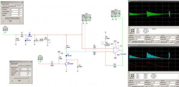
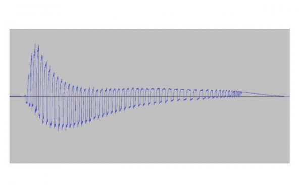
Old thread I know.. possibly everybody has moved on. But I just build Eric Archers Mini Space Rockers (they are awesome btw) with 3 rotary switches to choose between caps. Everything works fine. Only thing I've noticed is that, when triggered with a slow gate, there is a little lift at the end of each beat. Now I'm wondering if I messed up somewhere and if there is anything I can do to change it, or filter it out somehow..
| Description: |
|
| Filesize: |
14.54 KB |
| Viewed: |
1146 Time(s) |
| This image has been reduced to fit the page. Click on it to enlarge. |
|
| Description: |
|
Download (listen) |
| Filename: |
msr.mp3 |
| Filesize: |
452.99 KB |
| Downloaded: |
1281 Time(s) |
|
|
|
Back to top
|
|
|
PHOBoS

Joined: Jan 14, 2010
Posts: 5873
Location: Moon Base
Audio files: 709
|
| Posted: Sun Jan 20, 2019 7:56 am Post subject:
|
|
|
ah the mini space rockers, I actually started on a drum machine once with 8 of those all with different component values, someday I'll finish it
I honestly don't remember if it is supposed to sound like that, could very well be so I am not much of help there. But the waviness you see in the
signal is most likely the result of an AC coupling cap. It's always bit of a compromise, a small cap will filter out the low frequencies, a large cap has
a slow responce.
edit: had a look at the schematic and I think it's normal. The sound is generated by an AMV and the frequency depends on the supply which
is how it is triggerd. So it will be higher as the voltage decreases.
_________________
"My perf, it's full of holes!"
http://phobos.000space.com/
SoundCloud BandCamp MixCloud Stickney Synthyards Captain Collider Twitch YouTube |
|
|
Back to top
|
|
|
gabbagabi

Joined: Nov 29, 2008
Posts: 652
Location: Berlin by n8
Audio files: 23
|
|
|
Back to top
|
|
|
|

 Forum index » DIY Hardware and Software » Lunettas - circuits inspired by Stanley Lunetta