| Author |
Message |
RingMad

Joined: Jan 15, 2011
Posts: 428
Location: Montreal, Canada
Audio files: 4
|
 Posted: Thu Oct 04, 2012 4:10 pm Post subject:
The 4023 PWM Oscillator, Obsession and Me Posted: Thu Oct 04, 2012 4:10 pm Post subject:
The 4023 PWM Oscillator, Obsession and Me
Subject description: Where/how do you draw the line?! |
  |
|
Where does one stop!?
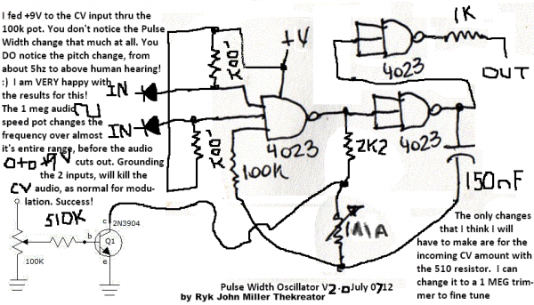
Last month I got obsessed with the CD4023 Pulse Width Oscillator that Rykhaard / Richarius had posted over on The Sound of Logic / Deathlehem forum. I found messages here mentioning it, but I could not find the schematic itself here.
So I built it and really loved it. Then, instead of working on my long-overdue suitcase synth, I became obsessed with automatizing several things with this circuit (which is now destined for said suitcase synth!)...
Then I ran it through my favorite triangle waveshaper (the 4015 & 4011, as found in this thread: http://electro-music.com/forum/topic-52443.html ).
Then I added the CV part to it, as devised by Rykhaard. Despite not being able to get the full range, it was still a lot of fun. I'd take the output of a 4-bit random generator into an R/2R and use that as a CV. Fun.
Then, wanting to replace the rotary switch that selects the capacitor in the circuit, I used a 4051 with 3 switches to choose 1 of 8 caps. But then of course, when one has an electronic switch, one can make that automatic. So 3 oscillators feed that, switching the cap. Crazy. Fun.
Then I eyed the feedback pot in the circuit. To replace it, I generate a voltage using a 4-bit random gen into an 2/2R. The resulting voltage feeds an LED in a home-rolled opto-isolator (AKA Vactrol), and the resulting resistance from the LDR is used instead of the pot. Crazy. Fun.
With all these things going at once, the sounds are pretty crazy. I tried adding slew/portamento/glide to one of the random CV's, but with all the cap-switching, it wasn't noticeable.
Almost all my breadboards are used, and they are sprawling all over the place.
And I want to further the self-playing ever-changing automaticness of this beast. I have some ideas, but I need a triangular VLFO, very slow, like 1 cycle per hour or maybe even 1 cycle per 17 minutes or something. I've had no luck with the old 4069 or LM324 LFO circuits. I have been racking my brain trying to figure out how to get a 4029 to count up then down all by itself. Anyway, that's possibly another thread.
There are 4 sound snippets posted on my soundcloud... (CMOSnippets #36 thru 39)... http://soundcloud.com/jamesschid .
This is a video of the earlier incarnation, with the CV input driven by a 4bit random generator into an R/2R : http://www.youtube.com/watch?v=JWXbtgKunJY . There's also a 4046 VCO following the same random voltage.
And I just shot a new video showing the last version, with the cap-switching and replaced feedback pot... http://www.youtube.com/watch?v=nJKgY3oQKI8 .
James. |
|
|
Back to top
|
|
 |
jcintheus

Joined: Oct 16, 2011
Posts: 59
Location: Colorado
|
| Posted: Thu Oct 04, 2012 10:32 pm Post subject:
|
|
|
I've also had alot of fun with this circuit! I made mine out of a 4093 and some mml. (I see you've seen)
As far as drawing a line, if you're really asking, who needs a line?
It looks like you cold develop quite a few different modules based on the same circuit.
Just keep notes!  |
|
|
Back to top
|
|
|
JingleJoe

Joined: Nov 10, 2011
Posts: 878
Location: Lancashire, England
Audio files: 14
|
| Posted: Fri Oct 05, 2012 12:51 am Post subject:
|
|
|
In answer to your first question:
One does not stop, one gets more shelves and more space and more parts and continues building the robots.
Carry on the good work and get something soldered up so you have some breadboard space again  remember to do a circuit diagram first. remember to do a circuit diagram first.
_________________
As a mad scientist I am ruled by the dictum of science: "I could be wrong about this but lets find out"
Green Dungeon Alchemist Laboratories |
|
|
Back to top
|
|
|
RingMad
Joined: Jan 15, 2011
Posts: 428
Location: Montreal, Canada
Audio files: 4
|
| Posted: Fri Oct 05, 2012 4:25 am Post subject:
|
|
|
| JingleJoe wrote: | | remember to do a circuit diagram first. |
Yeah, I have a lot of those to draw up. It's more fun making sounds, though. The "suitcase synth" is an insane undertaking... I'm afraid now that I have finalized the layout and modules therein.
"Robots making lots of cash and all they eat is instant mash"
James. |
|
|
Back to top
|
|
|
elmegil

Joined: Mar 20, 2012
Posts: 2179
Location: Chicago
Audio files: 16
|
| Posted: Fri Oct 05, 2012 5:45 am Post subject:
|
|
|
Any chance you can share that circuit from Deathlehem?
I have had nothing but bad luck with that site; first it took weeks to get approved, and then after finally being able to log in, now my account is no longer active or recognized.
I'm not upset with the owner or anything, I am just frustrated that it has been so difficult to work with the site. |
|
|
Back to top
|
|
|
RingMad
Joined: Jan 15, 2011
Posts: 428
Location: Montreal, Canada
Audio files: 4
|
|
|
Back to top
|
|
|
elmegil
Joined: Mar 20, 2012
Posts: 2179
Location: Chicago
Audio files: 16
|
| Posted: Fri Oct 05, 2012 12:45 pm Post subject:
|
|
|
Thanks
I'll give it another shot. |
|
|
Back to top
|
|
|
analog_backlash

Joined: Sep 04, 2012
Posts: 393
Location: Aldershot, UK
Audio files: 21
|
| Posted: Tue Oct 09, 2012 2:45 pm Post subject:
|
|
|
I find that no matter how many breadboards I have, I still manage to end up with them full of circuits. There must be some kind of law here - you can never have enough breadboard space. At the moment I have the randomizer, an experimental lunetta mixer, a slow-clocked white noise generator test circuit and a multi-synth mixer prototype all on the go. The answer is to commit them to PCB (or perfboard). The trouble is, I'm only 100% happy with the randomizer (I think). I think I'll do something about that tomorrow (although I always say that). Now, of course, I'd like to try out this 4023 circuit as well as hundreds more circuits that I've seen. I think that this website can only lead to madness (although I'm already there  ). ).
Keep up the good work,
Gary |
|
|
Back to top
|
|
|
RingMad
Joined: Jan 15, 2011
Posts: 428
Location: Montreal, Canada
Audio files: 4
|
| Posted: Wed Oct 10, 2012 5:18 am Post subject:
|
|
|
Committing to PCB/perfboard is tough for me. I want to make absolutely sure that I am 100% happy with the circuit, that the cap values and pot ranges are the most useful, etc. When I build a box, I usually still have the actual circuit still on the breadboards in case. And despite my careful planning, I still sometimes make changes to the box afterwards.
As for having a pile of circuits to try, well, yeah, this site certainly has a wealth of great ideas. It can be overwhelming as one's list gets longer and longer. I figure it's better to have lots of ideas than no ideas.
James. |
|
|
Back to top
|
|
|
analog_backlash
Joined: Sep 04, 2012
Posts: 393
Location: Aldershot, UK
Audio files: 21
|
| Posted: Wed Oct 10, 2012 5:46 am Post subject:
|
|
|
I also keep a breadboarded version on standby until I'm 100% happy with the hard-wired version. This is because, although I have a circuit diagram, I sometimes make small changes and forget to update the drawing/printout. Secondly, you can compare the performance of the 'properly' built one against the breadboard example (I have found the odd mistake at this stage). I once had a sample and hold circuit which worked perfectly well on the breadboard, but leaked alarmingly on PCB. It turned out that it was due to two tracks running close and parallel to each other. When I amended this, it worked. I think that it was down to the two tracks acting as a capacitor (but I'm still not totally sure).
As for the number of ideas, I'm glad that there are so many here. It's which one to try next that's my problem...
Cheers,
Gary |
|
|
Back to top
|
|
|
RingMad
Joined: Jan 15, 2011
Posts: 428
Location: Montreal, Canada
Audio files: 4
|
|
|
Back to top
|
|
|
PHOBoS

Joined: Jan 14, 2010
Posts: 5850
Location: Moon Base
Audio files: 709
|
|
|
Back to top
|
|
|
RingMad
Joined: Jan 15, 2011
Posts: 428
Location: Montreal, Canada
Audio files: 4
|
| Posted: Tue Oct 01, 2013 2:54 pm Post subject:
|
|
|
| PHOBoS wrote: | | are you gonna make a patchmatrix too ? |
Nope! |
|
|
Back to top
|
|
|
JingleJoe
Joined: Nov 10, 2011
Posts: 878
Location: Lancashire, England
Audio files: 14
|
| Posted: Wed Oct 09, 2013 2:05 pm Post subject:
|
|
|
I'm interested in how that oscillator acctually works or acheives PWM, I just breadboarded the above circuit diagram with a different kind of IC (2 input NOR) thinking this would work because it's basically the dual inverter oscillator with some extras, but it didn't work.
I honestly didn't expect it to but the note on the circuit diagram got my hopes up.  It half worked, I ghot a bit of frequency deviation but hardly any and it only changed one half of the duty cycle, as I expected it might from the way transistors work. It half worked, I ghot a bit of frequency deviation but hardly any and it only changed one half of the duty cycle, as I expected it might from the way transistors work.
Must it be a 4023? if so, why? has anyone acctually got it working exactly like it is in the diagram?
_________________
As a mad scientist I am ruled by the dictum of science: "I could be wrong about this but lets find out"
Green Dungeon Alchemist Laboratories |
|
|
Back to top
|
|
|
RingMad
Joined: Jan 15, 2011
Posts: 428
Location: Montreal, Canada
Audio files: 4
|
| Posted: Thu Oct 10, 2013 8:32 am Post subject:
|
|
|
Alas, I've forgotten any discussion or explanations from the original thread on Deathlehem, which are now lost forever. There was mention that one could use a different chip than the 4023 (possibly only 2 inputs are needed, and if faulty memory serves, someone built it with a 4093?).
As for whether it really does PWM, I don't know... I never actually checked or cared... I just liked what I was hearing, and just assumed that Ryk had named it accurately.
James. |
|
|
Back to top
|
|
|
brock

Joined: May 26, 2011
Posts: 112
Location: Canada
|
| Posted: Fri Oct 11, 2013 8:39 pm Post subject:
|
|
|
| Quote: | | I'm interested in how that oscillator acctually works or acheives PWM, I just breadboarded the above circuit diagram with a different kind of IC (2 input NOR) thinking this would work because it's basically the dual inverter oscillator with some extras, but it didn't work. |
It will work with NORs. You just need to change the 100k pull-up to pull-down and reverse the diode if you want gating capability. |
|
|
Back to top
|
|
|
JingleJoe
Joined: Nov 10, 2011
Posts: 878
Location: Lancashire, England
Audio files: 14
|
| Posted: Sat Oct 12, 2013 3:07 pm Post subject:
|
|
|
I thought so, however I noted almost no effect fron the voltage control transistor: it changed the time of one half of the duty cycle then cut out after some really dodgy high frequency oscillation at one specific control voltage.
I'm really interested to get the effect that the original poster acheived, this could be a fantastic VCO but I'm thinking perhaps the diagram is wrong? I'll have to do some more tests, does anyone have any ideas?
_________________
As a mad scientist I am ruled by the dictum of science: "I could be wrong about this but lets find out"
Green Dungeon Alchemist Laboratories |
|
|
Back to top
|
|
|
RingMad
Joined: Jan 15, 2011
Posts: 428
Location: Montreal, Canada
Audio files: 4
|
| Posted: Mon Nov 11, 2013 8:53 am Post subject:
|
|
|
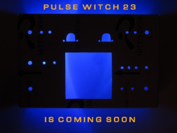
PULSE WITCH 23 IS HERE!
After an insane amount of work and logistics, it is finally done!
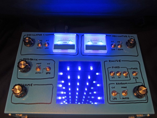
Basically, each of the 4 basic parameters of the circuit has several options... they can be adjusted manually or automatically (the latter via LFO or external CV). The idea is that the box can be played performatively, or used as a standalone installation.
For each section, a couple of switches, a pot and a 4053 allow one to use the pot manually directly, or as the speed control for the LFO.
Feedback level is controlled by a hand-rolled "vactrol" LED-LDR.
The range section is a bit more complicated: 8 different capacitors can be selected manually via the 3-bit switches (thus interfacing a 4051), or pseudo-randomly. The latter uses a 4006 & 4070 3-bit generator, whose clock rate can be controlled manually or automatically.
LFOs are triangular, based on a simple 40106 circuit. The end result of everything is made triangular via a 4015 wave-shaper.
The cool feature of the box is of course is the infinity mirror. The LEDs therein echo the state or value of the various sections, e.g. oscillator rate, feedback level and range choice (3 bit), 2 LEDs each. The meters show the internal voltage level ultimately controlling the speed of the oscillators.
For Burroughs and the "23 enigma" watchers... the main circuit uses a CMOS 4023 chip, the range on the meters go from 2 to 23 (in prime numbers, and VdGG units (because I was heavy into Peter Hammill & Van der Graaf Generator during part of the design phase)).
Thanks to Ryk for the original 4023 circuit, JingleJoe for invaluable assistance and circuits, PHOBoS for inspiration, and all y'all here in the electro-music forums for circuits, inspiration and moral support.
Demo video at http://www.youtube.com/watch?v=Tdb6NEecAUU :
-- James.
| Description: |
|
| Filesize: |
175.62 KB |
| Viewed: |
442 Time(s) |
| This image has been reduced to fit the page. Click on it to enlarge. |
|
|
|
|
Back to top
|
|
|
elmegil
Joined: Mar 20, 2012
Posts: 2179
Location: Chicago
Audio files: 16
|
| Posted: Mon Nov 11, 2013 9:22 am Post subject:
|
|
|
| RingMad wrote: | | For Burroughs and the "23 enigma" watchers... the main circuit uses a CMOS 4023 chip, the range on the meters go from 2 to 23 (in prime numbers, and VdGG units (because I was heavy into Peter Hammill & Van der Graaf Generator during part of the design phase)). |
Hail Eris!
That is a brilliant display, btw. |
|
|
Back to top
|
|
|
PHOBoS
Joined: Jan 14, 2010
Posts: 5850
Location: Moon Base
Audio files: 709
|
|
|
Back to top
|
|
|
blue hell
Site Admin

Joined: Apr 03, 2004
Posts: 24454
Location: The Netherlands, Enschede
Audio files: 297
G2 patch files: 320
|
| Posted: Mon Nov 11, 2013 10:07 am Post subject:
|
|
|
Niice! Beepwise and looks :-)
_________________
Jan
also .. could someone please turn down the thermostat a bit.
 |
|
|
Back to top
|
|
|
Cynosure
Site Admin

Joined: Dec 11, 2010
Posts: 1006
Location: Toronto, Ontario - Canada
Audio files: 82
|
| Posted: Mon Nov 11, 2013 12:44 pm Post subject:
|
|
|
| Awesome machine! Nice work. The mirror thing is a cool addition. |
|
|
Back to top
|
|
|
brock
Joined: May 26, 2011
Posts: 112
Location: Canada
|
| Posted: Mon Nov 11, 2013 3:57 pm Post subject:
|
|
|
| Very nice machine! The infinity mirror is a great touch and I like the backlit meters too. |
|
|
Back to top
|
|
|
analog_backlash
Joined: Sep 04, 2012
Posts: 393
Location: Aldershot, UK
Audio files: 21
|
| Posted: Mon Nov 11, 2013 6:09 pm Post subject:
|
|
|
Fantastic Ringmad! I'm looking up DIY infinity mirrors as we speak. I would never have guessed that (I thought that it might be some kind of 2D touch controller in that square).
My first post for a while - been feeling a bit low, but you've cheered me up  . .
Well worth the wait...
Gary |
|
|
Back to top
|
|
|
-minus-
Joined: Oct 26, 2008
Posts: 787
Audio files: 13
|
| Posted: Mon Nov 11, 2013 7:07 pm Post subject:
|
|
|
Excellent!  I was sucked right into the vortex at the end of your video. Reminds me of this game for some reason: Tempest! I was sucked right into the vortex at the end of your video. Reminds me of this game for some reason: Tempest!
|
|
|
Back to top
|
|
|
|

 Forum index » DIY Hardware and Software » Lunettas - circuits inspired by Stanley Lunetta