| Author |
Message |
mrmrshoes
Joined: Feb 19, 2011
Posts: 73
Location: Newcastle Upon Tyne
Audio files: 4
|
 Posted: Wed Jun 26, 2013 3:15 am Post subject:
ARP 4027-1 VCO Saw Core Posted: Wed Jun 26, 2013 3:15 am Post subject:
ARP 4027-1 VCO Saw Core |
  |
|
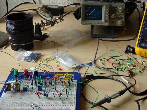
I've just finished Breadboarding the Arp 4027-1 Saw-Core and this thing is pretty cool so I thought I would post my findings. I must say that I’m no expert I’ve just been following the resources on the internet and hoping for the best.
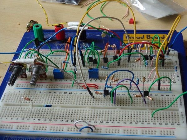
When I come to building this VCO I didn't want to use any hard to get parts so after consulting Andy1960 ARP VCO thread I replaced the ca3046 with unmatched 2n3904 transistors.
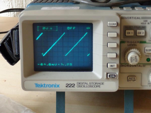
Check out the pictures of the VCO core on the breadboard and the resulting Ramp wave form using 2n3904/2n3906 and 2n5457 transistors.
Sure you can still get the ca3046 but a 100 2n3904 is about the the same price as a couple of chips and a lot easier to get hold of, this fact sells it to me every time.
The only hard to get part will be the JFET's seeing that someone thought it was a good idea to cease production. The good news is that I tried every JFET I had to hand and the circuit kept purring away.
Here is a list of JFET's I used with no noticeable differences
2n5457
2n5485
2n3819
J201
I couldn’t test the BF245 because the batch of 50 I bought are duds which I must say is pretty disappointing. I do believe this JFET should work because I’ve seen people stating these fellas as a working substitute.
The main resources I used for this project are found here:
4027-1 VCO schematic
http://www.till.com/arptech/modmain.htm
Bergfotron Basic VCO
http://hem.bredband.net/bersyn/VCO/vco_basic.htm
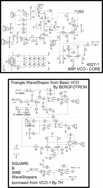
I breadboarded the original schematic first of all. The wave-shape was nice looking and sounded good. They was a little offset when testing. I then implemented Bergfotron resistor value changes to the vco core. They are about 5 value changes. These changes seem to correct the DC offset on the Ramp output.
I decided to implemented Bergfotron triangle wave-shaper. This wave-shaper uses commonly available parts which is a bonus. I decided to leave out the CV controlled switch circuity on the Bergfotron basic VCO. but the addition of a square, sine saw and ramp output + - 5V would be very useful. For the square and sine shapers I decided to use Thomas Henry circuits from his VCO-1 design. The triangle output is the correct amplitude for the wave-shaper inputs.
The sine wave-shape might need a bit of tweaking. If so you will want to read details on TH VCO-1 page, I've just left the value stated on the vco-1 schematic.
http://www.birthofasynth.com/Thomas_Henry/Pages/VCO-1.html
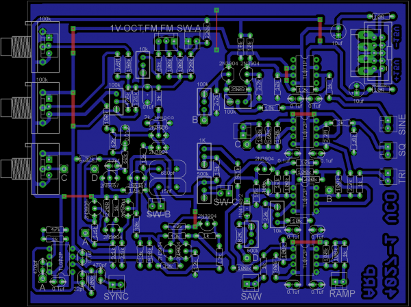
I've added my redrawn schematics
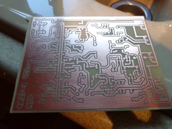
I’m planning on laying out a single sided PCB and I’ll post it here when it's built and tested.
| Description: |
|
| Filesize: |
6.38 MB |
| Viewed: |
407 Time(s) |
| This image has been reduced to fit the page. Click on it to enlarge. |
|
| Description: |
|
| Filesize: |
6.29 MB |
| Viewed: |
412 Time(s) |
| This image has been reduced to fit the page. Click on it to enlarge. |
|
| Description: |
|
| Filesize: |
6.43 MB |
| Viewed: |
371 Time(s) |
| This image has been reduced to fit the page. Click on it to enlarge. |
|
| Description: |
|
| Filesize: |
102.21 KB |
| Viewed: |
1833 Time(s) |
| This image has been reduced to fit the page. Click on it to enlarge. |
|
Last edited by mrmrshoes on Thu Jun 27, 2013 10:27 am; edited 2 times in total |
|
|
Back to top
|
|
 |
elmegil

Joined: Mar 20, 2012
Posts: 2179
Location: Chicago
Audio files: 16
|
| Posted: Wed Jun 26, 2013 6:18 am Post subject:
|
|
|
NICE  |
|
|
Back to top
|
|
|
mrmrshoes
Joined: Feb 19, 2011
Posts: 73
Location: Newcastle Upon Tyne
Audio files: 4
|
| Posted: Fri Jun 28, 2013 7:03 pm Post subject:
|
|
|
Cheers man 
I've tested the waveshapers over the pass couple of days and they work well.
Wave forms look good but I did have to make one change to the sine output. R64 & R65 were changed from 12k to 15k because i using + / - 12V supply and the resulting output was a bit weak.
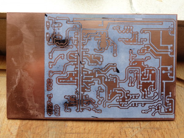
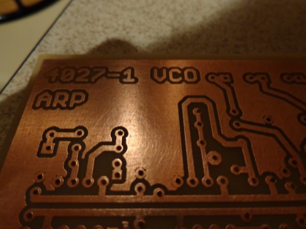
Also I'm getting a wee bit of bleed on the triangle output from the saw core but I'm putting this down to the state of my breadboard and a lack of de-coupling caps. I'm going to push on and see how a clean build works outs. I've designed this single sided PCB. I need to refine it abit but it's getting there.
Last edited by mrmrshoes on Tue Jul 02, 2013 7:58 am; edited 1 time in total |
|
|
Back to top
|
|
|
mrmrshoes
Joined: Feb 19, 2011
Posts: 73
Location: Newcastle Upon Tyne
Audio files: 4
|
| Posted: Sat Jun 29, 2013 9:59 am Post subject:
|
|
|
Ha, I'm such a dumb ass sometimes.
They ain't no bleed through from the VCO Core on the triangle output, it's harmonic content generated from the glitch in the waveform. I increased R77 from the schematic above to 82k and this considerable reduced this effect.
The input resistor for the PWM control (R53) needs tweeked aswell. I used 560K to set the pots range.
I think i'll add the opiton on the PCB for a trim pot for the triangle glitch resistor seeing that the value needed will change depending on the JFETS used within the circuit. |
|
|
Back to top
|
|
|
LFLab
Joined: Dec 17, 2009
Posts: 497
Location: Rosmalen, Netherlands
|
| Posted: Sat Jun 29, 2013 11:01 am Post subject:
|
|
|
Looks great!
Interesting footprint for the potmeters, is that for both 16mm and 9mm pc-mount pots? |
|
|
Back to top
|
|
|
mrmrshoes
Joined: Feb 19, 2011
Posts: 73
Location: Newcastle Upon Tyne
Audio files: 4
|
| Posted: Sat Jun 29, 2013 11:40 am Post subject:
|
|
|
cheers dude, glad you dig it like.
The footprint is a 16mm pot with a 0.1 header lumped together. It will give me the option of PCB mounted pots or the use of headers depending on how i choose to mount the PCB to a panel. It seemed like a good idea at the time, I don't even think about it anymore when I'm laying out a board.
To be honest i haven't paneled anything up yet so I not sure how useful it will be.  |
|
|
Back to top
|
|
|
mrmrshoes
Joined: Feb 19, 2011
Posts: 73
Location: Newcastle Upon Tyne
Audio files: 4
|
|
|
Back to top
|
|
|
steffensen

Joined: Jul 11, 2012
Posts: 103
Location: Sweden
|
| Posted: Tue Jul 02, 2013 8:52 am Post subject:
|
|
|
Pure Awesomeness!!! 
Cant wait to get my hands on that!
I have made the ARP 2600 AD/ADSR on a dual sided board in Eagle as well, just awaiting the boards to arrive. (about 4 weeks i guess)
Soon we'll have the many ARP parts yes. |
|
|
Back to top
|
|
|
mrmrshoes
Joined: Feb 19, 2011
Posts: 73
Location: Newcastle Upon Tyne
Audio files: 4
|
| Posted: Wed Jul 03, 2013 10:58 am Post subject:
|
|
|
| Quote: | Pure Awesomeness!!!
Cant wait to get my hands on that!
|
Thanks alot dude. If other people find this useful, it make the effort worth while
I've just put in an parts order so if all goes well the files will be up in a couple of weeks or so.
Your work on the ADSR/AD Envelope sounds interesting like. Could you supply more info on that if possible. Have you used substitute Transistors in your build. If the transistors and Jet’s in this build could be subbed for more common parts I’m defos up for building this and other ARP modules.
Also I've read somewhere that you can't sub the LM301 OP-AMP because of the way it functions, but you can still get hold of these so shouldn't be a problem.
I'll keep you updated with progress man
take it easy
mrmrshoes |
|
|
Back to top
|
|
|
jackdamery
Joined: Apr 26, 2010
Posts: 75
Location: UK
|
| Posted: Thu Jul 04, 2013 4:55 am Post subject:
|
|
|
| super awesome-o 5000 |
|
|
Back to top
|
|
|
steffensen
Joined: Jul 11, 2012
Posts: 103
Location: Sweden
|
| Posted: Thu Jul 04, 2013 9:31 am Post subject:
|
|
|
| mrmrshoes wrote: |
Your work on the ADSR/AD Envelope sounds interesting like. Could you supply more info on that if possible. Have you used substitute Transistors in your build. If the transistors and Jet’s in this build could be subbed for more common parts I’m defos up for building this and other ARP modules.
Also I've read somewhere that you can't sub the LM301 OP-AMP because of the way it functions, but you can still get hold of these so shouldn't be a problem.
I'll keep you updated with progress man
take it easy
mrmrshoes |
I of course meant the ADSR and AR (not AD). Working long hours until the vacation kicks in on Saturday. Then ill have the time/energy to try my design - when it arrives from the factory that is.
As im planning on doing it on 12v, i suspect i will have to do some tweaks to it. It might work straight off however, hoping for that.
I have implemented a Schmitt-trigger in the circuit to make sure the input trigger is above 10v, as thats the threshold for this circuit to work.
I am using 2N3906/3904's all the way thru, besides for the 2N5459 & 2N5460. Also sticking with the LM301 as i like that old grit. These parts are perhaps not to most available ones, but still pretty easy to get hold of.
I know several other IC's that would work too, but as said, i like to stick with the original path as much as i can.
Once ive made it work, i will experiment with some easier to find FET's, to really make this thing as easy to make as possible.
Gonna stop hogging up this thread now. I'll let you know if/when this thing is up and running. |
|
|
Back to top
|
|
|
Jerry_100
Joined: Nov 18, 2011
Posts: 6
Location: Bavaria
|
| Posted: Tue Jul 09, 2013 9:29 am Post subject:
|
|
|
| Excellent Job ! I like your board, keep on rolling..... |
|
|
Back to top
|
|
|
mrmrshoes
Joined: Feb 19, 2011
Posts: 73
Location: Newcastle Upon Tyne
Audio files: 4
|
| Posted: Tue Jul 09, 2013 2:51 pm Post subject:
|
|
|
Thanks alot fellas.
I've been having computer problems the pass 3-days. My laptop decided to die on me. I had feared for my hard drive. It contained all my PCB work. I got sloppy and didn't back up regularly. The Good news is that i have managed to pull all of my work onto another computer aswell as a stick/ external drive.
hopefully i'll have a prototype PCB made up in the next couple of days. Just need to double check the schematics and we should be ready to rock.
Please bear with me chaps. |
|
|
Back to top
|
|
|
Baloo
Joined: Jul 09, 2013
Posts: 16
Location: France
|
| Posted: Tue Jul 09, 2013 4:40 pm Post subject:
|
|
|
Nice work.
I am working in ARP Odyssey MK3 VCA & VCF
When I wil finish I will upload pictures of them. I even don´t know if they will work !! |
|
|
Back to top
|
|
|
Paradigm X
Joined: Feb 15, 2011
Posts: 363
Location: Null and void
Audio files: 2
|
| Posted: Fri Jul 12, 2013 2:42 am Post subject:
|
|
|
Hey mrmrshoes!
Hope youre well.
Glad to see youre still on it!
Cheers
Ben |
|
|
Back to top
|
|
|
mrmrshoes
Joined: Feb 19, 2011
Posts: 73
Location: Newcastle Upon Tyne
Audio files: 4
|
|
|
Back to top
|
|
|
isak

Joined: Dec 13, 2009
Posts: 847
Location: Israel
Audio files: 18
|
| Posted: Sat Jul 13, 2013 12:22 pm Post subject:
|
|
|
Great looking board
I'm watching this post for awhile now, happy to see you have progressed.
I etched a board of the vco 2 of the arp2600, it's with waveshapres to tri and sine, didn't built it yet.
I really can't find the post of the vco 2, sorry, but I have all the documents if you want me to upload
Cheers.

_________________
http://www.myspace.com/mgmtrance |
|
|
Back to top
|
|
|
Baloo
Joined: Jul 09, 2013
Posts: 16
Location: France
|
Posted: Sun Jul 14, 2013 2:38 am Post subject:
 |
|
|
@Isak- Could you upload the layout for the Arp2600 vco-2 ?
I would like try to build it.
|
|
|
Back to top
|
|
|
isak
Joined: Dec 13, 2009
Posts: 847
Location: Israel
Audio files: 18
|
|
|
Back to top
|
|
|
Baloo
Joined: Jul 09, 2013
Posts: 16
Location: France
|
| Posted: Sun Jul 14, 2013 2:25 pm Post subject:
|
|
|
| Thanks!! |
|
|
Back to top
|
|
|
mrmrshoes
Joined: Feb 19, 2011
Posts: 73
Location: Newcastle Upon Tyne
Audio files: 4
|
| Posted: Wed Jul 17, 2013 4:12 pm Post subject:
|
|
|
Sorry for wait fellas
I finally managed to finish the documentation for this VCO like, It took longer than I thought but its done now.
I've tested the majority of the circuit: VCO Core, LF mode, Saw, Ramp, Triangle, Square and Sine Wave-shaper circuity and all looks good. I should state that I’ve not had time to test external input functions of the VCO like 1V-Oct, FM and Sync but saying that I don't really see any issues arising from these things. Just be warned, if you build this project it at your own risk.
If you want extra documentation on calibrating the wave shapers or general back ground reading check out all of these sites:
4027-1 VCO schematic
http://www.till.com/arptech/modmain.htm
Bergfotron - Basic VCO
http://hem.bredband.net/bersyn/VCO/vco_basic.htm
Thomas Henry - wave-shapers schematics
http://www.birthofasynth.com/Thomas_Henry/Pages/VCO-1.html
AndyR1960 - great thread – ARP Odyssey Oscillators
http://electro-music.com/forum/topic-28604.html
Also a VERY big thank you to ARP, Bergfotron, Thomas Henry and Andy1960 for the resources related to this great VCO.
I'll probably update Build doc PDF with a basic run down of trimming the various wave-shaper parts of the circuit. I won't be able to do that for a few days, So keep an eye out.
enjoy!
| Description: |
|

Download (listen) |
| Filename: |
4027-1-VCO_Schematic.pdf |
| Filesize: |
354.2 KB |
| Downloaded: |
741 Time(s) |
| Description: |
|
Download (listen) |
| Filename: |
4027-1_VCO_BOM.pdf |
| Filesize: |
59.36 KB |
| Downloaded: |
529 Time(s) |
| Description: |
|
Download (listen) |
| Filename: |
4027-1-VCO_Press n Peel.pdf |
| Filesize: |
27.51 KB |
| Downloaded: |
568 Time(s) |
| Description: |
|
Download (listen) |
| Filename: |
4027-1_VCO_parts placement.pdf |
| Filesize: |
484.94 KB |
| Downloaded: |
580 Time(s) |
| Description: |
|
Download (listen) |
| Filename: |
4027-1 VCO build doc.pdf |
| Filesize: |
954.94 KB |
| Downloaded: |
612 Time(s) |
|
|
|
Back to top
|
|
|
isak
Joined: Dec 13, 2009
Posts: 847
Location: Israel
Audio files: 18
|
| Posted: Sat Jul 20, 2013 12:25 pm Post subject:
|
|
|
thank you very much my friend, great job!
i hope it sounds good as it look
did you matched any of the transistor?
the sync... is it in or out?
thanks again
_________________
http://www.myspace.com/mgmtrance |
|
|
Back to top
|
|
|
mrmrshoes
Joined: Feb 19, 2011
Posts: 73
Location: Newcastle Upon Tyne
Audio files: 4
|
| Posted: Sat Jul 20, 2013 1:24 pm Post subject:
|
|
|
Cheers pal.
You are more than welcome.
It sounds good like (good old ARP)
I didn't match a single transistor (It can't hurt if you do) and I got the waveform outputs shown in the VCO Build Doc PDF.
The Sync is Input. I just added Bergfotron's sync from his Basic VCO design.
Check out the schematic to get a feel for it.
The Triangle ain't a 100% clean, but you can trim it pretty close.
take it easy man
shoes |
|
|
Back to top
|
|
|
isak
Joined: Dec 13, 2009
Posts: 847
Location: Israel
Audio files: 18
|
|
|
Back to top
|
|
|
koenpepping
Joined: Jun 25, 2014
Posts: 8
Location: utrecht NL
|
| Posted: Wed Jul 09, 2014 4:33 am Post subject:
|
|
|
Hi,
first of all thanks for sharing the vco
I was looking at the BOM and noticed the ST3P switch.
my question is:
what does it do? and where can i find one?
thanks again and already! |
|
|
Back to top
|
|
|
|

 Forum index » DIY Hardware and Software