| Author |
Message |
RingMad

Joined: Jan 15, 2011
Posts: 429
Location: Montreal, Canada
Audio files: 4
|
 Posted: Wed Mar 25, 2015 3:31 pm Post subject:
"Sea Breeze" Pinball Lightbox Posted: Wed Mar 25, 2015 3:31 pm Post subject:
"Sea Breeze" Pinball Lightbox
Subject description: with even more complicated electronical illumination animation than last time |
  |
|
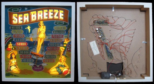
I finally finished the "Sea Breeze" Lightbox, made using a circa 1949 pinball backglass. The electronic circuit controls general illumination, as well as two chaser circuits, one of which changes speed periodically. It's just to look pretty on a wall... it makes no sound, nor is it part of a pinball machine.
DEMO VIDEO: https://vimeo.com/122848906 .
It was a lot of work, but it turned out nicely, and the guys I made it for love it. Thank you to PHOBoS for advice and sanity-checking re the ULNs.
"Sea Breeze" was the first of two pinball machine models ever produced in Canada, manufactured circa 1949 by the North Star Coin Machine Company of Montreal (yay! my hometown!)
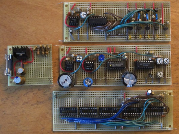
Circuit details:
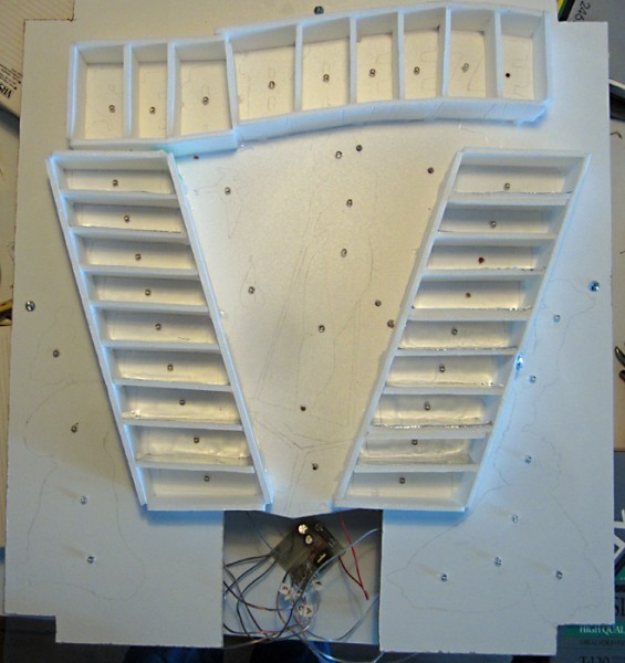
* Runs on 12V regulated supply. Contains 45 warm white "straw hat" LEDs.
* The S-E-A-B-R-E-E-Z-E chaser is 9 LEDs, and was adapted from Bill Marsden's "comet trails" chaser circuit using a CD4017 and transistor drivers (see fig. 12.3 D on allaboutcircuits: http://forum.allaboutcircuits.com/blog/leds-555s-pwm-flashers-and-light-chasers-index.378/ ).
* The "scores" chaser is 18 LEDs, and uses Bill Bowden's "18 Stage LED Sequencer" circuit with 2 CD4017's, but with 3 ULN2003 transistor arrays to drive the LEDs ( see http://www.bowdenshobbycircuits.info/page5.htm#4017-7.gif).
* There is a mode timer which will enable/disable the chasers such that only one is running at any one time. Diode steering is used so that when the "scores" chaser is running, the S-E-A-B-R-E-E-Z-E letters are all lit.
* There is also a speed control timer circuit for the "scores" chaser, same thing I used in my first pinball lightbox (see my post http://electro-music.com/forum/topic-61960.html ). This consists of a CD4046 VCO which serves as the clock for the chaser counters. The timer switches between the VCO being fed by a large capacitor, or nothing. When it's nothing, the VCO runs at its base speed, which is set at about 1s. When it switches to the capacitor, the voltage goes from the 12V and discharges in about 30-40s, hence the clock speeds up to its maximum, back down to the base speed.
* The actual mode and speed switching is handled by a CD4053. The timers and clocks (except for the 4046) are good ol' CMOS 555's.
* For general illumination, i.e. the LEDs which are always on (the girls, the bird and the sailboat), there are 6 strings of 3, 2, or 1 LEDs in series.
.: James
.: www.jamesschidlowsky.ca :.
| Description: |
| Front and back of the box. |
|
| Filesize: |
362.87 KB |
| Viewed: |
541 Time(s) |
| This image has been reduced to fit the page. Click on it to enlarge. |
|
| Description: |
| Light panel with isolators. |
|
| Filesize: |
264.41 KB |
| Viewed: |
580 Time(s) |
| This image has been reduced to fit the page. Click on it to enlarge. |
|
| Description: |
|
| Filesize: |
351.74 KB |
| Viewed: |
520 Time(s) |
| This image has been reduced to fit the page. Click on it to enlarge. |
|
|
|
|
Back to top
|
|
 |
PHOBoS

Joined: Jan 14, 2010
Posts: 5881
Location: Moon Base
Audio files: 709
|
|
|
Back to top
|
|
|
RingMad
Joined: Jan 15, 2011
Posts: 429
Location: Montreal, Canada
Audio files: 4
|
| Posted: Sat Mar 28, 2015 5:08 am Post subject:
|
|
|
Thanks, PHOBoS!
Yeah, the warm white LEDs are yellower than the cool white, and thus closer to the incandescent bulbs that would have been used on the old pinball machines. The photo doesn't quite do it justice, though... LEDs are tricky to photograph.
I've never dealt with, nor do I have any real interest at this point in Arduino. But I admit I was wondering if certain things would be easier if I used a PICAXE, like I've used in a few projects. The 18-stage chaser was pretty confusing to build.
But then, I don't immediately see how to control that many LEDs from one chip.
Plus, one still has to build all the drivers.
.: James :. |
|
|
Back to top
|
|
|
PHOBoS
Joined: Jan 14, 2010
Posts: 5881
Location: Moon Base
Audio files: 709
|
| Posted: Sat Mar 28, 2015 6:33 am Post subject:
|
|
|
I've never used an arduino either, but they seem popular. I do use some simple PICs (PIC16F628a) from time to time
but I prefer circuits with simple chips. The fibonacci generator is a good example of that. It would have been be very easy
to have build that using a single PIC.
| Quote: | But then, I don't immediately see how to control that many LEDs from one chip.
Plus, one still has to build all the drivers. |
shiftregisters are your friends here, they make it possible to create as many in/outputs as you want. (and yes you would still need the drivers)
It wouldn't really save you anything in hardware but once that is build you can program it to display whatever patterns you want.
_________________
"My perf, it's full of holes!"
http://phobos.000space.com/
SoundCloud BandCamp MixCloud Stickney Synthyards Captain Collider Twitch YouTube
Last edited by PHOBoS on Mon Mar 30, 2015 6:30 am; edited 1 time in total |
|
|
Back to top
|
|
|
RingMad
Joined: Jan 15, 2011
Posts: 429
Location: Montreal, Canada
Audio files: 4
|
| Posted: Mon Mar 30, 2015 4:06 am Post subject:
|
|
|
Hmmm, I'll have to look at the shift-register thing. I had come across a circuit like that before but didn't quite understand how it worked... I guess it's worth studying that closer.
Of course for this particular project since it's dealing with a very old backglass, I wanted pretty simple chasers... stuff that would be closer to the kind of thing that could have been done in that era.
.:James:. |
|
|
Back to top
|
|
|
PHOBoS
Joined: Jan 14, 2010
Posts: 5881
Location: Moon Base
Audio files: 709
|
| Posted: Mon Mar 30, 2015 6:29 am Post subject:
|
|
|
I use the 74HCT595 for outputs as a serial to parallel converter and the 74HCT165 for inputs as a parallel to serial converter.
They require 3 pins of your PIC but if you use them both they can share the CLK. So with only 5 pins you can have as many
in/outs as you want. Of course the more you add the slower the maximum speed will be. I think I have an example schematic
on how to connect is somewhere, will post it IF I can find it.
Here's an example of where I used that setup  : :

_________________
"My perf, it's full of holes!"
http://phobos.000space.com/
SoundCloud BandCamp MixCloud Stickney Synthyards Captain Collider Twitch YouTube |
|
|
Back to top
|
|
|
|

 Forum index » Discussion » Schmooze » Miscellaneous DIY Art
