| Author |
Message |
artilect99
Joined: Oct 01, 2018
Posts: 51
Location: USA
|
 Posted: Mon Mar 11, 2019 12:56 pm Post subject:
Ian Fritz Chaos Gen Stripboard Layout - Standalone Rungler Posted: Mon Mar 11, 2019 12:56 pm Post subject:
Ian Fritz Chaos Gen Stripboard Layout - Standalone Rungler |
  |
|
Hi all,
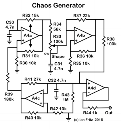
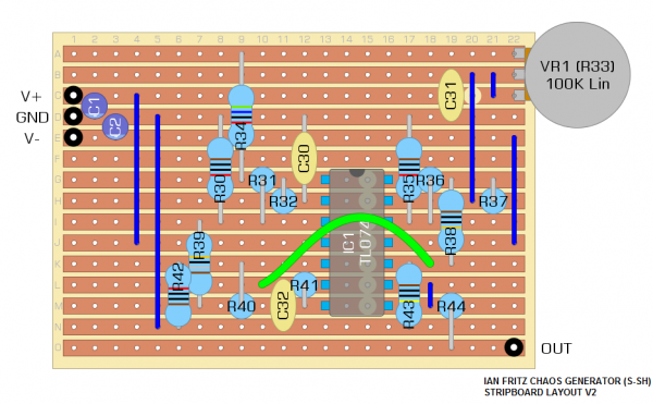
I'm new to laying out stripboards, and I wanted to do something simple, so along with the magic smoke 8k LFO I attempted this circuit, which is the voltage source from Ian Fritz' Super Sample & Hold.
I haven't built this one yet, but I thought I'd post my layout here and see if any of you stripboard gurus notice anything glaringly and embarrassingly wrong with it!  It's literally my 2nd layout ever, so I would be shocked if it didn't. It's literally my 2nd layout ever, so I would be shocked if it didn't.
Below is the layout and the original schematic.
| Description: |
|
| Filesize: |
63.86 KB |
| Viewed: |
19887 Time(s) |
|
| Description: |
|
| Filesize: |
82.28 KB |
| Viewed: |
629 Time(s) |
| This image has been reduced to fit the page. Click on it to enlarge. |
|
Last edited by artilect99 on Tue Mar 12, 2019 6:48 pm; edited 1 time in total |
|
|
Back to top
|
|
 |
artilect99
Joined: Oct 01, 2018
Posts: 51
Location: USA
|
| Posted: Tue Mar 12, 2019 10:30 am Post subject:
|
|
|
Hm, I take it by the lack of reply that my stripboarding skills are beyond reproach!  This is glad news indeed! This is glad news indeed!
just kidding, I will build it out and see if it works. If there are problems I'll update it accordingly, just in case anyone else wants to build this. Personally I was excited by this circuit, seems like a simple, low-overhead way to add a random voltage without the need for a drive signal. Maybe it is too similar to white noise to be of much use in practice? We shall see... |
|
|
Back to top
|
|
|
artilect99
Joined: Oct 01, 2018
Posts: 51
Location: USA
|
| Posted: Tue Mar 12, 2019 6:47 pm Post subject:
|
|
|
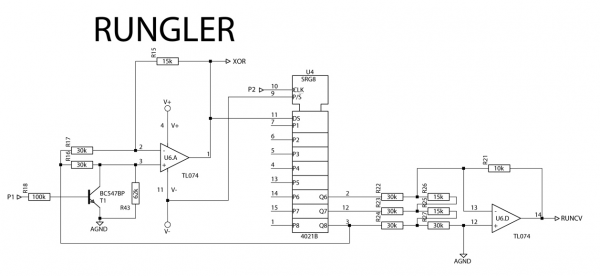
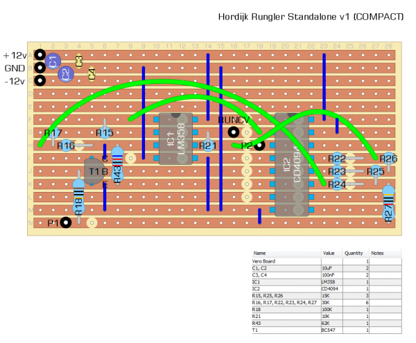
Here's an attempt at a standalone Rungler. Thought I'd post it here rather than start a new thread... any corrections would be much appreciated. (I'm sure there's a way to do it in a lot less board space, but right now I just want to get it working.) Subbed a 4094 IC so it can run off +12v.
| Description: |
|
| Filesize: |
91 KB |
| Viewed: |
855 Time(s) |
| This image has been reduced to fit the page. Click on it to enlarge. |
|
| Description: |
|
| Filesize: |
114.85 KB |
| Viewed: |
645 Time(s) |
| This image has been reduced to fit the page. Click on it to enlarge. |
|
Last edited by artilect99 on Thu Mar 14, 2019 3:25 pm; edited 1 time in total |
|
|
Back to top
|
|
|
gabbagabi

Joined: Nov 29, 2008
Posts: 652
Location: Berlin by n8
Audio files: 23
|
| Posted: Wed Mar 13, 2019 9:38 am Post subject:
|
|
|
u need to forgive the forum members for not responding,
controlling stripboard designs that u not have done urself is not the most enjoy-able activity 
eventhought ur design looking quite clear. |
|
|
Back to top
|
|
|
elmegil

Joined: Mar 20, 2012
Posts: 2179
Location: Chicago
Audio files: 16
|
| Posted: Wed Mar 13, 2019 12:17 pm Post subject:
|
|
|
Your Rungler is going to blow up.
In the original circuit the rails are +9 and -9, and the 4021 is powered from +9 to -9.
While you're running your 4094 off of 0 -> 12V so it won't have a problem there, you're running your op amp at +/-12V and that will fry the data in on the 4094 when it's low.
You *should* be able to get away with using a single-supply op amp instead of the TL072 (it will *not* work without a balanced supply). I'm not having any luck finding single op amps with single supply (I know they exist, but I can't remember, and my datasheets will take a long time to sift through), but you could use an LM358 for example and just ground the inputs of the second amp. |
|
|
Back to top
|
|
|
artilect99
Joined: Oct 01, 2018
Posts: 51
Location: USA
|
| Posted: Thu Mar 14, 2019 8:37 am Post subject:
|
|
|
| g.gabba wrote: | | controlling stripboard designs that u not have done urself is not the most enjoy-able activity |
For sure. I was just putting them up to get a second set of eyes, in case there was anything immediately apparent that was obviously wrong -- such as
| elmegil wrote: | | Your Rungler is going to blow up. |
good catch elmegil. I see input voltages are supposed to be between -0.5v and supply +0.5v. Could I use a diode rectifier or a similar scheme to kill the negative half of the waveform? |
|
|
Back to top
|
|
|
elmegil
Joined: Mar 20, 2012
Posts: 2179
Location: Chicago
Audio files: 16
|
| Posted: Thu Mar 14, 2019 8:40 am Post subject:
|
|
|
| artilect99 wrote: | | elmegil wrote: | | Your Rungler is going to blow up. |
good catch elmegil. I see input voltages are supposed to be between -0.5v and supply +0.5v. Could I use a diode rectifier or a similar scheme to kill the negative half of the waveform? |
Not sure..... That sounds reasonable, but I don't know for certain, I haven't done that kind of trickiness much. |
|
|
Back to top
|
|
|
artilect99
Joined: Oct 01, 2018
Posts: 51
Location: USA
|
| Posted: Thu Mar 14, 2019 9:07 am Post subject:
|
|
|
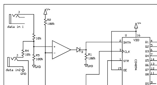
Am I understanding correctly that the problem is the TL072 is going to be ouptutting a negative voltage in it's "low" state instead of 0v?
In that case I was thinking something like this:
 |
|
|
Back to top
|
|
|
elmegil
Joined: Mar 20, 2012
Posts: 2179
Location: Chicago
Audio files: 16
|
| Posted: Thu Mar 14, 2019 1:21 pm Post subject:
|
|
|
Correct in concept, however, it's usually not just that simple.
For one example, going forward through the diode, you will lose 1 diode drop. That *should* be fine, but may not be. CMOS chips like the high value to be very close to the + rail.
For another, when you're reversed and the diode is cut off, there is not actually a "ground" signal at the input of the 4094, so that also may not work, or worse, only work intermittently. I'd consider putting a 10K to ground on that side of the diode.
But this is all just GENERAL advice, I have not tested any of it nor do I have specific expertise addressing -V into chips that can't tolerate -V. |
|
|
Back to top
|
|
|
artilect99
Joined: Oct 01, 2018
Posts: 51
Location: USA
|
| Posted: Thu Mar 14, 2019 3:22 pm Post subject:
|
|
|
Using LM358 for the op-amp seems like the easiest way then... good call!
Should the strobe pin 1 be tied high? |
|
|
Back to top
|
|
|
elmegil
Joined: Mar 20, 2012
Posts: 2179
Location: Chicago
Audio files: 16
|
| Posted: Thu Mar 14, 2019 4:08 pm Post subject:
|
|
|
You'll still need to address the possibility of a negative going input, but it won't be as difficult with an op amp There are examples of this with op amp inputs available in schematics for things like the Orgone Accumulator which is open source.
As for strobe, that's how I would read the verbiage at the start, but the timing diagram is confusing me. You'll need to look at that more, or maybe just use the 4021 like the original. |
|
|
Back to top
|
|
|
artilect99
Joined: Oct 01, 2018
Posts: 51
Location: USA
|
| Posted: Mon Apr 08, 2019 10:52 am Post subject:
|
|
|
I'm a little unclear as to how the original circuit deals with negative going inputs?
for what its worth I'm not trying to make a commercial product, I just need it to work in my own setup, so if that comes with some caveats like "dont send it bipolar LFOs or you will fry it" thats fine. |
|
|
Back to top
|
|
|
artilect99
Joined: Oct 01, 2018
Posts: 51
Location: USA
|
| Posted: Mon Apr 08, 2019 10:58 am Post subject:
|
|
|
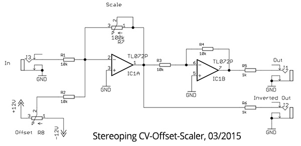
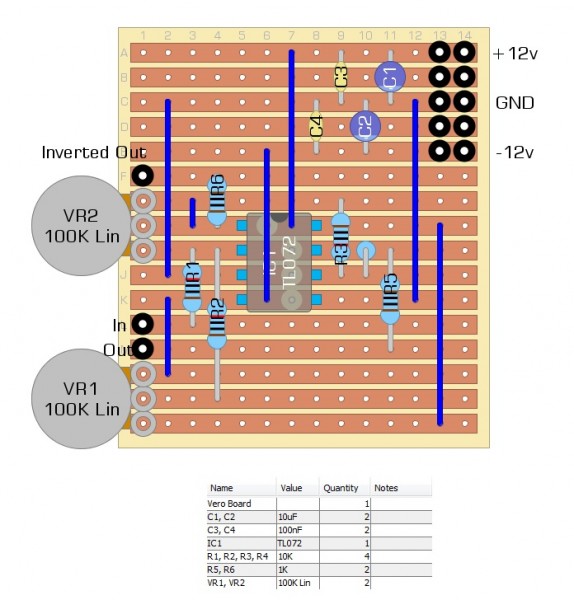
Here's one for Stereoping's Scaler/Offset utility module.
| Description: |
|
| Filesize: |
28.3 KB |
| Viewed: |
19140 Time(s) |
|
| Description: |
|
| Filesize: |
136.34 KB |
| Viewed: |
803 Time(s) |
| This image has been reduced to fit the page. Click on it to enlarge. |
|
|
|
|
Back to top
|
|
|
artilect99
Joined: Oct 01, 2018
Posts: 51
Location: USA
|
|
|
Back to top
|
|
|
artilect99
Joined: Oct 01, 2018
Posts: 51
Location: USA
|
| Posted: Wed Sep 07, 2022 7:48 pm Post subject:
|
|
|
lol building that Rungler on stripboard sent me down a long rabbit hole of shift register sequencers and LFSR noise. And somehow I ended up right back at this thread by accident.
Anyway, with the benefit of actually understanding the circuit now:
The reason the rungler doesn't "blow up" as Elmegil suggested is because the input stage is a comparator that only puts out high (+Vcc) or low (0v) states for the shift register.
The register bits are sent to an R-2R dac whose output is (on the benjolin) intended to be CV for a pair of VCOs, one clocking the shift register and the other fed into the comparator input (P1).
The result is a bewildering array of "interference patterns"
The reason I wanted a standalone rungler is to basically patch up a benjolin with pre-existing VCOs, but this got me obsessed with shift register sequencers such as the CGS gated comparator, Wiard Noisering, Turing Machine, and the mighty Klee. |
|
|
Back to top
|
|
|
|

 Forum index » DIY Hardware and Software » The layout factory