| Author |
Message |
THeff

Joined: Sep 01, 2006
Posts: 229
Location: Florida
Audio files: 33
|
|
|
Back to top
|
|
 |
Nosferatu

Joined: Jul 27, 2007
Posts: 234
Location: Planet Rock.
|
 Posted: Wed Oct 10, 2007 5:26 am Post subject:
Re: Synbal noise / cymbal circuit Posted: Wed Oct 10, 2007 5:26 am Post subject:
Re: Synbal noise / cymbal circuit |
  |
|
Synbal, syntom, syndrum.
Edit: Many thanks to bluhell for maintaining thread consistency.
Last edited by Nosferatu on Thu Oct 18, 2007 1:07 pm; edited 2 times in total |
|
|
Back to top
|
|
|
fluxmonkey
Joined: Jun 24, 2005
Posts: 708
Location: cleve
|
| Posted: Wed Oct 10, 2007 10:03 am Post subject:
|
|
|
THeff,
thanks for posting this... as i posted before, there's plenty of precidence for mixing multiple oscs together via gates, nice to see another example in the context of this discussion. including a filter has obvious advantages, a'la MFOS's WeirdSoundGenerator... would be great to get the PCB layout if you don't mind.
and gratitutde extends to anyone who goes out of their way to post information to add to the collective knowbase... your generosity deserves only praise, not public scolding...
b |
|
|
Back to top
|
|
|
THeff
Joined: Sep 01, 2006
Posts: 229
Location: Florida
Audio files: 33
|
| Posted: Wed Oct 10, 2007 3:30 pm Post subject:
Synbal...more info |
|
|
Hi bbob,
Thanks for noticing the similarity!
Hmmm...let me see 6 cmos oscillators using 40106 inverters, mixed with 4070 xor gates, and a pitch adjustment by setting the oscillator B+ voltage. Seems rather similar to the schematic at the top of this thread!
The Synbal is only a percussion device if you use it that way. Change the feedback resistors in the cmos oscillators with potentiometers and you will get amazing "machine sounds". You also get a white noise generator, nice voltage controlled filter, trigger circuit, and stereo panning.
I only mentioned it on this thread to let people know that the pcb from this article is on the web and might make it a lot easier to build.
I was going to remove it until I noticed that it had been viewed 12 times, so I guess there is some interest out there.
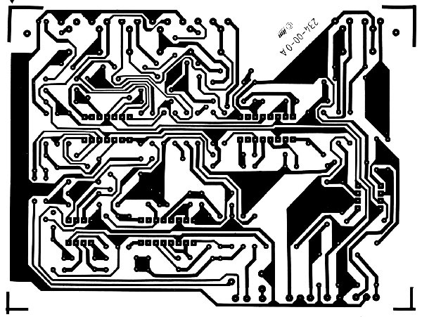
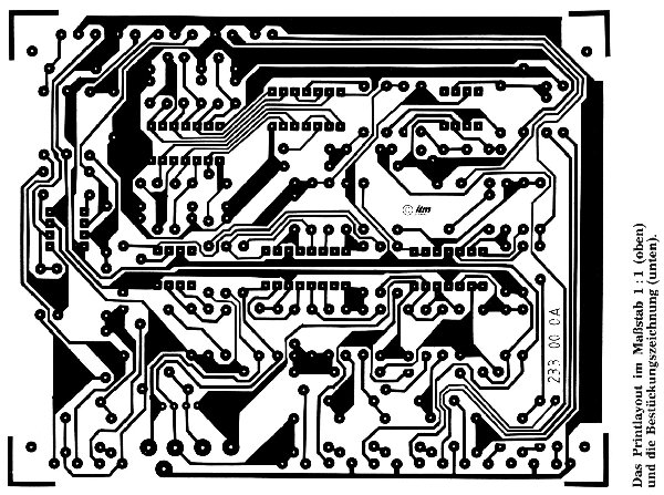
Anyway, the pcb is attached and I will add the rest of the article to show the parts placement on the pcb. The article was scanned by a guy that goes by the name "Synth Ollie" so he gets all the credit! 
Enjoy,
Tim
| Description: |
|
| Filesize: |
418.48 KB |
| Viewed: |
1593 Time(s) |
| This image has been reduced to fit the page. Click on it to enlarge. |
|
| Description: |
|
| Filesize: |
678.19 KB |
| Viewed: |
1418 Time(s) |
| This image has been reduced to fit the page. Click on it to enlarge. |
|
| Description: |
|
| Filesize: |
709.41 KB |
| Viewed: |
1324 Time(s) |
| This image has been reduced to fit the page. Click on it to enlarge. |
|
| Description: |
|
| Filesize: |
809.14 KB |
| Viewed: |
1550 Time(s) |
| This image has been reduced to fit the page. Click on it to enlarge. |
|
|
|
|
Back to top
|
|
|
blue hell
Site Admin

Joined: Apr 03, 2004
Posts: 24499
Location: The Netherlands, Enschede
Audio files: 298
G2 patch files: 320
|
| Posted: Wed Oct 10, 2007 4:22 pm Post subject:
Re: Synbal...more info |
|
|
| THeff wrote: | | Seems rather similar to the schematic at the top of this thread! |
Yup, I think so. Still this is developing into a new project that deserves a thread of it's own. So I'll be splitting off some posts to a new topic "Synbal".
_________________
Jan
also .. could someone please turn down the thermostat a bit.
 |
|
|
Back to top
|
|
|
factus10
Joined: Jun 20, 2007
Posts: 158
Location: Buffalo, NY
|
| Posted: Wed Oct 10, 2007 5:32 pm Post subject:
|
|
|
Awesome! I've been thinking about the EM&M drum circuits of late. So... what about the Syntom, etc  |
|
|
Back to top
|
|
|
THeff
Joined: Sep 01, 2006
Posts: 229
Location: Florida
Audio files: 33
|
|
|
Back to top
|
|
|
synth_ollie

Joined: Sep 11, 2006
Posts: 149
Location: sweden
|
| Posted: Wed Oct 10, 2007 11:37 pm Post subject:
Re: Synbal...more info |
|
|
| THeff wrote: | The article was scanned by a guy that goes by the name "Synth Ollie" so he gets all the credit!
|
I guess that must be me then!  |
|
|
Back to top
|
|
|
23isgood

Joined: Nov 18, 2006
Posts: 236
Location: San Francisco, CA bay area
Audio files: 13
|
| Posted: Thu Oct 11, 2007 1:43 am Post subject:
|
|
|
This circuit is almost exactly like Ken Stone's, Cynare. I would like to build one of these.
_________________
Check out my music |
|
|
Back to top
|
|
|
THeff
Joined: Sep 01, 2006
Posts: 229
Location: Florida
Audio files: 33
|
Posted: Thu Oct 11, 2007 9:02 am Post subject:
 Greetings to Synth Ollie Greetings to Synth Ollie |
|
|
Hi Synth Ollie!
We have never spoken before, but thank you for scanning these pages. I have made several of the Synbal and Syntom II pcbs as a result of your efforts and they work great. I perfboarded the MIDI/Trigger section from Trevor Pages's 9090 and it works very well as the controller for Synbal, Syntom II and other misc. percussion circuits floating around. I have also triggered these guys from the Klee 2 sequencer and that was fun. I want to setup a complete percussion section similar to the Russian link that was on YouTube. It looks like the web link for the Russian sight has been removed.
Thanks again!
Regards,
Tim |
|
|
Back to top
|
|
|
Scott Stites
Janitor


Joined: Dec 23, 2005
Posts: 4127
Location: Mount Hope, KS USA
Audio files: 96
|
| Posted: Thu Oct 11, 2007 7:29 pm Post subject:
|
|
|
| Quote: | | your generosity deserves only praise, |
Especially in light of the fact you're the only guy I know who could perf the thing up in the time it took to write the post
_________________
My Site |
|
|
Back to top
|
|
|
THeff
Joined: Sep 01, 2006
Posts: 229
Location: Florida
Audio files: 33
|
Posted: Thu Oct 11, 2007 9:08 pm Post subject:
 Perfboards... Perfboards... |
|
|
Thanks Scott, but I must of told you a million times not ro exaggerate!
Tim |
|
|
Back to top
|
|
|
ickystay
Joined: Nov 15, 2006
Posts: 143
Location: Oregon
|
| Posted: Wed Oct 17, 2007 8:18 pm Post subject:
|
|
|
| Big thanks to synth_ollie! |
|
|
Back to top
|
|
|
San
Joined: Mar 13, 2012
Posts: 4
Location: Poland, Warsaw
|
| Posted: Mon Sep 10, 2012 11:58 pm Post subject:
|
|
|
| Anyone with music samples? |
|
|
Back to top
|
|
|
n.d

Joined: Dec 15, 2011
Posts: 52
Location: Talos IV
|
|
|
Back to top
|
|
|
Ruebezahl

Joined: Mar 09, 2014
Posts: 112
Location: Taiwan
Audio files: 4
|
| Posted: Fri Aug 22, 2014 8:24 am Post subject:
|
|
|
Hi!
I am trying to build the synbal (and later the syntom) right now. Already etched the board, and i am shopping for the parts now. Apparently some of the semi-conductors are not avaivable easily anymore. I wanted to ask the people who already built it or who could guess by experience, to suggest alternatives. Note, that i am not really picky, and take whatever sounds more or less the same. i dont care much, if it sounds exactly like the original one
IC2: "LM13600", an amplifier chip with 16 pins. "Dual transconductance amplifier", its used at two points in the circuit. first for buffering the envelope, wich is coming out of the decay-control. second for filtering of the signal.----when i searched for this ic i got a result for an LM13700, wich would be available. after a quick internet seach it seems to be very closely related, and also pincompatible. seems like i could use this one instead, but i better ask here before.
IC3: "CA3080" Its, like the LM13600 an operational transconductance Amplifier, and the predecessor of said chip. apparently i could use LM13700 if it was just for the function. but it has much more pins and is not pincompatible. so any help here?
Edit: i just found this chip on reichelt, a german onlineshop. but its 10€ with shipping. plus i read about fake chips around, so i dont know, better have an alternative.
IC4: "741". Not sure about this one. If the LM741 is meant by this its no problem. i think i even still have one at home.
IC101: "4558 or TL1458". According to the text its used in the final stereo mixing stage. i dont even find a datasheet for TL1458 and for 4558 i find several different chips, but just one of them has 8 pins, like needed. Its the RC4558 P, wich you can find here: http://www.segor.de/#Q%3DRC4558P%26M%3D1
do you think this one is suitable? also i am not sure if this final stereo mixing stage is needed if i want just a mono out. there is something in the text about it, but i am not sure if a understood already.
Thanks for your help!
_________________
https://soundcloud.com/ruebezahl |
|
|
Back to top
|
|
|
wackelpeter
Joined: May 05, 2013
Posts: 461
Location: germany
Audio files: 10
|
|
|
Back to top
|
|
|
Ruebezahl
Joined: Mar 09, 2014
Posts: 112
Location: Taiwan
Audio files: 4
|
| Posted: Sun Aug 24, 2014 4:09 am Post subject:
|
|
|
Thanks for the reply. Unfortunately i build this circuits based on the pcb-Layout posted her, so i etched a circuit board. this makes it impossible to just use the 13700 for the CA3800 since it has more pins. the only thing i could imagine, would be, to make bridges from the desginated pin-holes to a second board where i have the chip soldered to. if i make the bridges very short and take a very small piece of board, just big enough for the chip, it should be not to complicated and even look neat  just have to make sure the solder-points of the second board dont touch the first board anywhere. just have to make sure the solder-points of the second board dont touch the first board anywhere.
I would like to NOT order at reichelt, because they charge 6€ on shipping, and actually all other chips (including the 741 and 4558) i could get at segor in their shop here in berlin, so i would save the shipping.
_________________
https://soundcloud.com/ruebezahl |
|
|
Back to top
|
|
|
donpachi
Joined: Jul 16, 2009
Posts: 81
Location: Marburg
Audio files: 2
|
| Posted: Wed Aug 27, 2014 11:39 am Post subject:
|
|
|
| CA3080 is available at http://www.uk-electronic.de/ for E2,20. Shipping costs are very reasonable starting from E2,00. Not meaning to advertise, I am just a happy recurrent customer |
|
|
Back to top
|
|
|
Ruebezahl
Joined: Mar 09, 2014
Posts: 112
Location: Taiwan
Audio files: 4
|
| Posted: Sun Sep 21, 2014 4:29 pm Post subject:
|
|
|
So i am building these both modules now. The Synbal one is almost done
But i am wondering how i will trigger them later. Since they are originally designed for use with a drumpad, they are normally triggered by a piezo. But i want to use them in a modular setup, together with a Hip Bass Drum. So i want to use the same trigger Signal for all the drum modules.
In the descriptions for the syntom it says very vaguely that triggering by a "rythm machine" is also possible. but no word about how high should the Voltage be.
In the description of the synbal, they say a trigger signal can be "up to 5V", or even more if you adjust R2.
The Hip Bass Drum, i was building expects something between 5V and 10V. So i guess i go for 5V. Any thoughts on that?
Lets say i go for the 5V-Trigger-Signal. I would probably do this with a Schmitt Trigger like the 40106. But if i power it with the same +-15V Supply, i use for the drum modules, the pulse it puts out, will be also between -15V and +15V, or not? So i could use a tip on how to generate those 5V-Pulses.
And after i achieved this, i still need to turn the pulse into shorter Trigger, right? For this, someone recommended me this module http://www.cgs.synth.net/modules/cgs24_gatetotrigger.html
I will probably build everything in one module, with just the trigger out. i dont see the use of gate signals in drum machines, or would there be?
Well lots of Questions, wich are also for a big part just very loosely related to the Synbal and Syntom. But i would be very happy if someone could help me.
_________________
https://soundcloud.com/ruebezahl |
|
|
Back to top
|
|
|
PHOBoS

Joined: Jan 14, 2010
Posts: 5881
Location: Moon Base
Audio files: 709
|
| Posted: Mon Sep 22, 2014 3:05 am Post subject:
|
|
|
| Ruebezahl wrote: |
Lets say i go for the 5V-Trigger-Signal. I would probably do this with a Schmitt Trigger like the 40106. But if i power it with the same +-15V Supply, i use for the drum modules, the pulse it puts out, will be also between -15V and +15V, or not? So i could use a tip on how to generate those 5V-Pulses. |
The maximum supply voltage for CMOS is usually 18V max, so you have to power it from GND/+15V
(or -15V/GND but that would result in negative output voltages)
5V on the output can be achieved with 2 resistors as a simple voltage divider, a resistor + zenerdiode,
or you could even use a voltage regulator (78L05).
But the Synbal already has an attentuator on the trigger input so it's not needed for that.
_________________
"My perf, it's full of holes!"
http://phobos.000space.com/
SoundCloud BandCamp MixCloud Stickney Synthyards Captain Collider Twitch YouTube |
|
|
Back to top
|
|
|
Ruebezahl
Joined: Mar 09, 2014
Posts: 112
Location: Taiwan
Audio files: 4
|
| Posted: Wed Sep 24, 2014 4:27 pm Post subject:
|
|
|
Thanks for your help!
One little question regarding the Gate to Trigger Converter:

Why there are TWO capacitors in parallel to each other? On the sketch its not really obvious they are parallel. I dont understand why there must be a capacitor between the poles in the first place, but i saw it on a lot of circuits before. but what sense does it to have those two in parallel. i am talking about the 10uF Elko and the 100nF one.
_________________
https://soundcloud.com/ruebezahl |
|
|
Back to top
|
|
|
blue hell
Site Admin
Joined: Apr 03, 2004
Posts: 24499
Location: The Netherlands, Enschede
Audio files: 298
G2 patch files: 320
|
| Posted: Wed Sep 24, 2014 4:35 pm Post subject:
|
|
|
The electrolytic one keeps the supply voltage rails clean for low frequencies, and the 100 nF one does the same for high frequencies, as the electrolytic one isnt so good there.
_________________
Jan
also .. could someone please turn down the thermostat a bit.
|
|
|
Back to top
|
|
|
prgdeltablues
Joined: Sep 25, 2006
Posts: 222
Location: UK
Audio files: 12
|
| Posted: Thu Sep 25, 2014 1:36 am Post subject:
|
|
|
Also, the electrolytic 10uF is usually placed where the power enters the board, and the 100n is placed as close to the pins on the IC as possible. Common practice is to have 100n capacitors for every chip on a board.
Peter |
|
|
Back to top
|
|
|
Ruebezahl
Joined: Mar 09, 2014
Posts: 112
Location: Taiwan
Audio files: 4
|
| Posted: Sun Sep 28, 2014 10:08 am Post subject:
|
|
|
Thanks for your answers, i learn something every day i am here I will write more about this circuit later... i am not sure if its working yet...
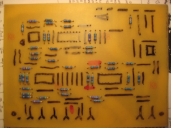
But so far something about the SyntomII. If anyone want to build this PCB after the Layout THeff posted here in this thread before:
1. Note that there are some holes were it might not be obvious later, because they are a tiny white spot, and like in my case, it might be no spot at all later, after etching. So in my case i missed some holes and had to drill them later, where i already populated it a bit. No big deal, but it might be good to know it in advance, so maybe you can change the layout a bit and make the holes a few pixels bigger. I am talking about the holes in the middle of the big black areas.
2. I dont know why but there will be 6 holes wich are not mentioned in the Component Overlay in the Scanned Article from F&MM '83. Maybe the scans are old or what do i know. But i took a picture of this 6 Holes (3 Connections). they are marked with red...I compared to the original schematics and found out that all of them are just simple links. But omitting them, would mean the schematic would not work, so i dont know why they are not on there. Any comments on that from the people who already built them?
| Description: |
|
| Filesize: |
120.12 KB |
| Viewed: |
582 Time(s) |
| This image has been reduced to fit the page. Click on it to enlarge. |
|
_________________
https://soundcloud.com/ruebezahl |
|
|
Back to top
|
|
|
|

 Forum index » DIY Hardware and Software