| Author |
Message |
jumunius
Joined: Apr 19, 2010
Posts: 346
Location: San Francisco, CA
Audio files: 13
|
|
|
Back to top
|
|
 |
janvanvolt

Joined: Nov 24, 2005
Posts: 285
Location: Mainz, Germany
|
 Posted: Fri Nov 12, 2010 6:57 am Post subject: Posted: Fri Nov 12, 2010 6:57 am Post subject:
|
  |
|
It seems i now get the idea behind creatorlars panel.
You are right with regards to the IMPACT pot. I rewired this and i get the whole
idea now:
- You take the outputs from Impact and noise and feed it to the IMPACT/NOISE pot.
- From there you use a 4K7 passive mixer for each of those pot and mix it together to the CV switched lug, from the lug to the CV Control pot.
This is now working as expected.
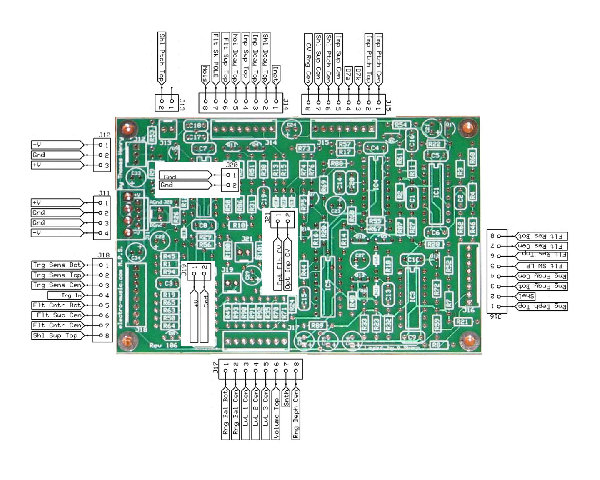
To answer various J21 Questions:
I have an old PCB silkscreen copy here, so it is _
- J21-1 to 10K resistor then to R65 (left bottom, 4th Resistor from bottom)
- J21-2 to 10K resistor then to R69 ( 3rd part left of IC4)
Working like a charm now  Thanks for all the support. Thanks for all the support.
I just tried it with GATE, but the real fun is with trigger, so i am trying it on with the Q960
_________________
Homepage - http://www.czmok.de
My dIY - http://diy.czmok.de
Film/Music - http://gfm.me |
|
|
Back to top
|
|
|
casperelectronics

Joined: Feb 13, 2008
Posts: 23
Location: Troy Ny usa
|
|
|
Back to top
|
|
|
casperelectronics
Joined: Feb 13, 2008
Posts: 23
Location: Troy Ny usa
|
| Posted: Thu Dec 30, 2010 9:21 pm Post subject:
|
|
|
| casperelectronics wrote: | C22 from .22uF to 1uF for short noise decay.
|
oops. I meant I switched C22 from 2.2uF to 1uF for a shorter noise decay. |
|
|
Back to top
|
|
|
jumunius
Joined: Apr 19, 2010
Posts: 346
Location: San Francisco, CA
Audio files: 13
|
| Posted: Tue Feb 01, 2011 2:16 am Post subject:
|
|
|
| casperelectronics wrote: | Did a bunch of range tweaking as well.
-increased filter resonance by switching the 20k range resistor (R46) with a 1k.
|
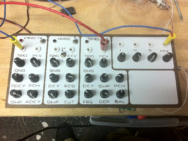
A lot of good tips there, thanks! I just "finished" my MPS tonight -- ok, it's bare metal... someday I will do a proper panel, and add some of those send/receive jacks plus a further mod here or there.
But I really appreciated the call-out to tweak R46. Added resonance ring really improves the noise filter, very useful for percussive sounds. However, in my build I found something more like 5.6k to be the right range. At 1k I was getting a bit too much distortion in the towards the top range of the pot, whereas at 5.6k, I can achieve a nice sharp ringing, and only on the very top 10% of the pot at LP setting do I start to get distortion.
For those interested, definitely give this a try. And if you, like me, are too lazy to desolder your board, just add a resistor between the leftmost (as seen from the rear) lug of your Resonance pot (R78) and ground. (This is the pad that connects to J16-8.) Since it will act in parallel with the existing 20k R46, a value of 8.2k achieves my desired setting of 5.6k (or so) and 1.1k would get you close to casperelectronics' 1k. Use a banana clip and try out a range to see what works for you. Check out response on both LP and BP too. |
|
|
Back to top
|
|
|
Luka

Joined: Jun 29, 2007
Posts: 1003
Location: Melb.
|
|
|
Back to top
|
|
|
tommi

Joined: Dec 05, 2007
Posts: 247
Location: Italy
Audio files: 3
|
|
|
Back to top
|
|
|
jordroid
Joined: Jan 17, 2010
Posts: 193
Location: ithaca, new york
|
| Posted: Sat Apr 02, 2011 10:01 am Post subject:
|
|
|
| Luka wrote: | hey does anyone know if i can alter the pcb so i can use 100k pots for every pot?
i have a tonne of pcb mount 100k pots and i want to use them before i puchase any more pots |
My semi uninformed answer is, maybe, but you would have to recalculate a bunch of stuff, and the non 100k pots may be there for a good reason.
The three 1 meg pots are variable resistors and control how quickly the EGs decay after a trigger pulse, a 100k pot here would cause them to decay much faster than the 1 meg pot, so maybe increasing the size of the associated cap would make the range workable? There is also a series resister in line with the pot, so you would probably want to mess with that as well to get the pot to feel nice. The noise decay, for instance looks like it is controlled by R12 and R95 in series, both in parallel with C22, maybe mess with them and see what happens? The potentiometers responsible for A,D and R functions of envelope generators are very often 1meg, my guess is that there is a good reason this is so.
The 10k pots seem to be there for impedance reasons? They are all voltage dividers, several of them hanging off transistor emitters, i'd be hesitant to mess with them before getting a more informed opinion than i am capable of, but the worst that could happen is the release of some magic smoke  I'm not sure about the sensitivity control R36, you could easily adjust the resistors on either side of it to have the same ratios? I think i remember reading that it took some tweaking to get the mixer section to work nicely, so messing with the 10k pots here may throw things off? It probably won't hurt anything to try adjusting the mixer section, but it seems like some work went into optimizing it. I'm not sure about the sensitivity control R36, you could easily adjust the resistors on either side of it to have the same ratios? I think i remember reading that it took some tweaking to get the mixer section to work nicely, so messing with the 10k pots here may throw things off? It probably won't hurt anything to try adjusting the mixer section, but it seems like some work went into optimizing it.
This post is partially to answer your question to the best of my abilities, and partially to lure smarter people out, in the hopes that they will feel compelled to correct any misinformation i have given you
regards,
jordan |
|
|
Back to top
|
|
|
jordroid
Joined: Jan 17, 2010
Posts: 193
Location: ithaca, new york
|
|
|
Back to top
|
|
|
tommi
Joined: Dec 05, 2007
Posts: 247
Location: Italy
Audio files: 3
|
| Posted: Sat Apr 02, 2011 6:02 pm Post subject:
|
|
|
Thanks jordan!
I had already readed Scott Stites explanation of the noise section and i ended up increasing the noise volume at the input of the LM13700.
R11, wich originally was 820 ohm, is there to pull down the volume of the noise to an acceptable level for the lm13700, wich can handle a maximum level of 20mV pp (talking about signal's average value).
Looking there with the scope it turned out that i could increase the volume. I calculated that, given the average value i measured r11 could be 2k. So i changed that resistor and now i have a better balance between the three voices.
cheers,
t
_________________
http://soundcloud.com/mister-vommi
http://tideofsound.net |
|
|
Back to top
|
|
|
Eraser127

Joined: Apr 20, 2010
Posts: 16
Location: Dordrecht, The Netherlands
|
| Posted: Mon Apr 11, 2011 12:55 pm Post subject:
|
|
|
Alright, i've got a bit of a problem:
i was busy moving my MPS from my cardboardbox to a 19" rackunit, when i accidentally touched a component (resistor? not sure) with my tweezers on the right side of the TL074 on the pcb. Now the MPS stopped working  I already replaced and tried the TL074, 4046 and the 2206 ic's but it's no good. Even when I replace one of the LM13700's it make's no use. I already replaced and tried the TL074, 4046 and the 2206 ic's but it's no good. Even when I replace one of the LM13700's it make's no use.
I looked at all the resistors and diodes and they seem to look fine. Could it be one of the transistors or something in the mixer area? I've gone over the scheme so many times that i've lost it right now.
Does anyone have an idea?
regards,
_________________
3630 Compressor | BCR2000, Ultrapatch Pro PX2000 | DR-220E | GX-700 | FX57 | Xboard25 | Small Clone, Small Stone, Big Muff, Electric Mistress Deluxe | Juli@, M8U | UE400 | Poly-61 (custom midi), 05R/W | Rokit RP-5 | MB33 | Nova, KS-Rack | MWR-01 MetalWorker | R8, MKS-50, PG-300, M-VS1, M-DC1, JP-8080, Juno-106, JX8P, PG-800 | Topaz Macro Plus | E816S | Cubase 5 | Softsynths | TH MPS | Pulse+Rekon Editor | AN1X |
|
|
Back to top
|
|
|
Eraser127
Joined: Apr 20, 2010
Posts: 16
Location: Dordrecht, The Netherlands
|
| Posted: Tue Apr 12, 2011 8:48 am Post subject:
|
|
|
I already checked the + and - voltages to the ic's and that's fine. Also in the cardboard box is worked fine
_________________
3630 Compressor | BCR2000, Ultrapatch Pro PX2000 | DR-220E | GX-700 | FX57 | Xboard25 | Small Clone, Small Stone, Big Muff, Electric Mistress Deluxe | Juli@, M8U | UE400 | Poly-61 (custom midi), 05R/W | Rokit RP-5 | MB33 | Nova, KS-Rack | MWR-01 MetalWorker | R8, MKS-50, PG-300, M-VS1, M-DC1, JP-8080, Juno-106, JX8P, PG-800 | Topaz Macro Plus | E816S | Cubase 5 | Softsynths | TH MPS | Pulse+Rekon Editor | AN1X |
|
|
Back to top
|
|
|
unterbit

Joined: Dec 08, 2008
Posts: 30
Location: Russia.St Petersburg
|
| Posted: Fri Apr 22, 2011 3:21 pm Post subject:
WiringSwitch#2,on MPS,HELP |
|
|
| Somebody can tell how he\she had wired switch#2,particularly Lp out,i cant find pad for it. |
|
|
Back to top
|
|
|
jumunius
Joined: Apr 19, 2010
Posts: 346
Location: San Francisco, CA
Audio files: 13
|
| Posted: Fri Apr 22, 2011 3:45 pm Post subject:
Re: WiringSwitch#2,on MPS,HELP |
|
|
| unterbit wrote: | | Somebody can tell how he\she had wired switch#2,particularly Lp out,i cant find pad for it. |
LP is J 16-5
Center is J14-7
BP is wired to Resonance "top" (where J16-6 is wired) |
|
|
Back to top
|
|
|
Eraser127
Joined: Apr 20, 2010
Posts: 16
Location: Dordrecht, The Netherlands
|
| Posted: Sat May 07, 2011 5:00 am Post subject:
|
|
|
| Eraser127 wrote: | Alright, i've got a bit of a problem:
i was busy moving my MPS from my cardboardbox to a 19" rackunit, when i accidentally touched a component (resistor? not sure) with my tweezers on the right side of the TL074 on the pcb. Now the MPS stopped working I already replaced and tried the TL074, 4046 and the 2206 ic's but it's no good. Even when I replace one of the LM13700's it make's no use.
I looked at all the resistors and diodes and they seem to look fine. Could it be one of the transistors or something in the mixer area? I've gone over the scheme so many times that i've lost it right now.
Does anyone have an idea?
regards, |
Yay, I got some sound out of it, even though the voltages to the ic's were there it doesn't mean the ic's are good ( d'oh). I replaced the "shell" and "impact" lm13700 and they work ok now (although the ringmod give's no sound). I also tried it with the "noise" opamp but that doesn't change anything and when I turn up the noise volume I get a hum, so I also need to fix that. At least i'm happy I got some sound out of it again. I'll just go on with my quest for sound 
_________________
3630 Compressor | BCR2000, Ultrapatch Pro PX2000 | DR-220E | GX-700 | FX57 | Xboard25 | Small Clone, Small Stone, Big Muff, Electric Mistress Deluxe | Juli@, M8U | UE400 | Poly-61 (custom midi), 05R/W | Rokit RP-5 | MB33 | Nova, KS-Rack | MWR-01 MetalWorker | R8, MKS-50, PG-300, M-VS1, M-DC1, JP-8080, Juno-106, JX8P, PG-800 | Topaz Macro Plus | E816S | Cubase 5 | Softsynths | TH MPS | Pulse+Rekon Editor | AN1X |
|
|
Back to top
|
|
|
worldbank
Joined: Nov 29, 2010
Posts: 2
Location: finland
|
| Posted: Sun Jun 12, 2011 7:24 am Post subject:
|
|
|
Heyy
i have 2 mps boards populated, now starting to wire them up.. but, as i look more of pics of your mps's i get more confused.. in some you have 4 pots for the noise section.. cutoff, res, decay, sweep.. some have also "sens" in there.. in some you have "center" ? whats going on.. what is this "center" ?
also.. is there somewhere clear instructions on how to add the separate trig inputs for the noise,impct and shell ?
thanks.. |
|
|
Back to top
|
|
|
jumunius
Joined: Apr 19, 2010
Posts: 346
Location: San Francisco, CA
Audio files: 13
|
| Posted: Sun Jun 12, 2011 1:46 pm Post subject:
|
|
|
| worldbank wrote: | Heyy
i have 2 mps boards populated, now starting to wire them up.. but, as i look more of pics of your mps's i get more confused.. in some you have 4 pots for the noise section.. cutoff, res, decay, sweep.. some have also "sens" in there.. in some you have "center" ? whats going on.. what is this "center" ?
|
The 4 pots for noise is the standard, exactly as you listed them. "Sens" is trigger sensitivity. I think casparelectronics was talking about adding separate triggers for each section, which is where the additional pot would come in. That would be a mod though and I don't think anyone has documented how to do that.
I don't know what "Center" is but maybe it's someone's term for "Ring Balance? Or BPF cutoff on the noise filter? For the most part, the Bugbrand wiring diagram found in this thread is the best resource in terms of official build wiring. But even it veers from the schematics. If you look back a couple pages I itemize a lot of the differences between Bugbrand's wiring and TH's original design. Comparing BB's wiring against the schematic (even if you aren't great w/ schematics) is a very useful exercise at this stage. |
|
|
Back to top
|
|
|
rumpofsteelskin
Joined: Apr 22, 2009
Posts: 52
Location: brighton, uk
|
| Posted: Tue Sep 20, 2011 12:14 pm Post subject:
|
|
|
hmmm.... just put together my (first!) MPS - is the impact generator 4046 meant to be triggered or is it just going all the time and the trig pulse opens the VCA? My impact generator sounds pretty weak and I can't figure out why......
definitely wouldn't be able to get the nice attack like here http://www.youtube.com/watch?v=6Tvn2nHs4lI |
|
|
Back to top
|
|
|
jumunius
Joined: Apr 19, 2010
Posts: 346
Location: San Francisco, CA
Audio files: 13
|
| Posted: Tue Sep 20, 2011 1:16 pm Post subject:
|
|
|
| rumpofsteelskin wrote: | | hmmm.... just put together my (first!) MPS - is the impact generator 4046 meant to be triggered or is it just going all the time and the trig pulse opens the VCA? |
Yup, it should be going all the time. When you are in "locked" mode (as opposed to trigger mode), everything is essentially going at once -- Impact, Shell, Noise, Ring.
I don't know what's going on for you but impact should sound significantly louder than Shell, since Impact is a square wave and Shell is a triangle wave. |
|
|
Back to top
|
|
|
rumpofsteelskin
Joined: Apr 22, 2009
Posts: 52
Location: brighton, uk
|
| Posted: Wed Sep 21, 2011 4:13 am Post subject:
|
|
|
| Yeah this impact generator doe not sound right/good I think something's a miss here.... I would have expected the impact to be triggered - otherwise you run the risk of getting two transients in quick succession on some hits and only one on others, depending where the VCA turns on in the wave.... are there any sound files (just the impact generator would be good) or measurements anywhere for reference? |
|
|
Back to top
|
|
|
jumunius
Joined: Apr 19, 2010
Posts: 346
Location: San Francisco, CA
Audio files: 13
|
| Posted: Wed Sep 21, 2011 11:00 am Post subject:
|
|
|
| rumpofsteelskin wrote: | | Yeah this impact generator doe not sound right/good I think something's a miss here.... I would have expected the impact to be triggered - otherwise you run the risk of getting two transients in quick succession on some hits and only one on others, depending where the VCA turns on in the wave.... are there any sound files (just the impact generator would be good) or measurements anywhere for reference? |
If I understand your triggering concern correctly, wouldn't the problem exist for both voices? Meaning, in an ideal world wouldn't you be triggering both waveforms to start from zero at the same time?
As for sound files, I would normally be happy to do that but I've disassembled my MPS in order to mod it a little. |
|
|
Back to top
|
|
|
Eraser127
Joined: Apr 20, 2010
Posts: 16
Location: Dordrecht, The Netherlands
|
| Posted: Tue Sep 27, 2011 5:00 am Post subject:
|
|
|
Alright, finally continued with the MPS and got some sound but there are 2 problems:
1. the BP/LP switch doesn't work although i hear the noise generator doing it's work. It just doesn't filter.
2. i built the thing inside a 2he 19" rack, but i got a grounding problem. The test build was in a cardboard box (see earlier posts) so there was no grounding problem. However now it's inside a metal box i hear a hum. The grounding points of the pots/jacks (some metal pots) are all connected to a small print with one wire to the power supply:

Can someone help me to finally get this thing ready?
_________________
3630 Compressor | BCR2000, Ultrapatch Pro PX2000 | DR-220E | GX-700 | FX57 | Xboard25 | Small Clone, Small Stone, Big Muff, Electric Mistress Deluxe | Juli@, M8U | UE400 | Poly-61 (custom midi), 05R/W | Rokit RP-5 | MB33 | Nova, KS-Rack | MWR-01 MetalWorker | R8, MKS-50, PG-300, M-VS1, M-DC1, JP-8080, Juno-106, JX8P, PG-800 | Topaz Macro Plus | E816S | Cubase 5 | Softsynths | TH MPS | Pulse+Rekon Editor | AN1X |
|
|
Back to top
|
|
|
TheAncientOne

Joined: Dec 26, 2006
Posts: 144
Location: United Kingdom
|
| Posted: Thu Sep 29, 2011 1:42 am Post subject:
|
|
|
Might be worth putting a 'scope on your power supply line: with a 12V AC wall wart and half-wave rectification, there is a chance that the regs may be dropping out on load, momentarily.
Just a thought, not a certainty, but worth checking, in my opinion.
If you don't have a 'scope, then a DVM set on 'AC Volts' might show a reading, indicating ripple on the supply line, (for certain, use the DVM with a series capacitor, say 100n, to block DC - some 'true RMS' meters will read an AC + DC total).
_________________
Mike |
|
|
Back to top
|
|
|
mosc
Site Admin

Joined: Jan 31, 2003
Posts: 18260
Location: Durham, NC
Audio files: 228
G2 patch files: 60
|
| Posted: Thu Sep 29, 2011 7:32 am Post subject:
|
|
|
| TheProf wrote: |
If you don't have a 'scope, then a DVM set on 'AC Volts' might show a reading, indicating ripple on the supply line, (for certain, use the DVM with a series capacitor, say 100n, to block DC. |
Great suggestion, Mike. A very simple idea that I've not heard before. And I thought I knew everything. 
_________________
--Howard
my music and other stuff |
|
|
Back to top
|
|
|
Eraser127
Joined: Apr 20, 2010
Posts: 16
Location: Dordrecht, The Netherlands
|
| Posted: Sun Oct 02, 2011 6:17 am Post subject:
|
|
|
Ok, checked the voltage and that seems to be fine. I've got the potmeters wired in a "star" shaped ground (all going to a print and one wire from print to J12). I also had to ground pin 12 of IC1 (LM13700) otherwise the noise won't trigger.
I'm glad the thing makes sound, but I want to completely get rid of the hum and want the LP/BP filter to work again.
_________________
3630 Compressor | BCR2000, Ultrapatch Pro PX2000 | DR-220E | GX-700 | FX57 | Xboard25 | Small Clone, Small Stone, Big Muff, Electric Mistress Deluxe | Juli@, M8U | UE400 | Poly-61 (custom midi), 05R/W | Rokit RP-5 | MB33 | Nova, KS-Rack | MWR-01 MetalWorker | R8, MKS-50, PG-300, M-VS1, M-DC1, JP-8080, Juno-106, JX8P, PG-800 | Topaz Macro Plus | E816S | Cubase 5 | Softsynths | TH MPS | Pulse+Rekon Editor | AN1X |
|
|
Back to top
|
|
|
|

 Forum index » DIY Hardware and Software » Thomas Henry designs