| Author |
Message |
akrearke
Joined: Sep 08, 2008
Posts: 53
Location: US
|
 Posted: Thu Dec 10, 2009 9:51 am Post subject:
Lunetta designs Posted: Thu Dec 10, 2009 9:51 am Post subject:
Lunetta designs |
  |
|
I post a lot if things here on electro music. Unfortunately, limited finances does not allow me to build most of the designs or finish them. However, I like to share... Here are my lunetta foils if anyone is interested. Most of them will be found on this site and others. The schematics are often included. as always they will have to be sized using the DIP pins. Thanks to everyone that provided the information. All remain untested...
| Description: |
|

Download (listen) |
| Filename: |
LUNETTA COMPLE WAVEFORM GENERATOR.bmp |
| Filesize: |
2.24 MB |
| Downloaded: |
2462 Time(s) |
| Description: |
|
Download (listen) |
| Filename: |
LUNETTA DUAL VCO ALPHA 3.bmp |
| Filesize: |
2.24 MB |
| Downloaded: |
2060 Time(s) |
| Description: |
|
Download (listen) |
| Filename: |
LUNETTA CD40106 DUAL VCO.bmp |
| Filesize: |
2.24 MB |
| Downloaded: |
2087 Time(s) |
|
|
|
Back to top
|
|
 |
RF

Joined: Mar 23, 2007
Posts: 1502
Location: Northern Minnesota, USA
Audio files: 28
|
| Posted: Fri Dec 11, 2009 6:41 am Post subject:
|
|
|
Thanks for sharing those akrearke...
bruce
_________________
www.sdiy.org/rfeng
"I want to make these sounds that go wooo-wooo-ah-woo-woo.”
(Herb Deutsch to Bob Moog ~1963) |
|
|
Back to top
|
|
|
electri-fire
Joined: Jul 26, 2006
Posts: 536
Location: Dordrecht NL
Audio files: 4
G2 patch files: 4
|
Posted: Mon Feb 22, 2010 4:47 am Post subject:
Subject description: Some Lunetta modules on e-chuck boards |
|
|
Some CMOS on Invertor's E-chucK boards.
| Description: |
|
| Filesize: |
103.34 KB |
| Viewed: |
1242 Time(s) |
| This image has been reduced to fit the page. Click on it to enlarge. |
|
| Description: |
|
| Filesize: |
113.34 KB |
| Viewed: |
1184 Time(s) |
| This image has been reduced to fit the page. Click on it to enlarge. |
|
| Description: |
|
| Filesize: |
74.4 KB |
| Viewed: |
797 Time(s) |
| This image has been reduced to fit the page. Click on it to enlarge. |

|
Last edited by electri-fire on Mon Feb 22, 2010 7:31 am; edited 1 time in total |
|
|
Back to top
|
|
|
electri-fire
Joined: Jul 26, 2006
Posts: 536
Location: Dordrecht NL
Audio files: 4
G2 patch files: 4
|
|
|
Back to top
|
|
|
Inventor
Stream Operator

Joined: Oct 13, 2007
Posts: 6221
Location: near Austin, Tx, USA
Audio files: 267
|
| Posted: Mon Feb 22, 2010 6:21 am Post subject:
|
|
|
electri-fire, thanks for posting these! Its nice to see those boards getting some good use now.
Les
_________________
"Let's make noise for peace." - Kijjaz |
|
|
Back to top
|
|
|
electri-fire
Joined: Jul 26, 2006
Posts: 536
Location: Dordrecht NL
Audio files: 4
G2 patch files: 4
|
|
|
Back to top
|
|
|
droffset

Joined: Feb 02, 2009
Posts: 515
Location: London area
Audio files: 2
|
|
|
Back to top
|
|
|
electri-fire
Joined: Jul 26, 2006
Posts: 536
Location: Dordrecht NL
Audio files: 4
G2 patch files: 4
|
| Posted: Tue Feb 23, 2010 4:40 am Post subject:
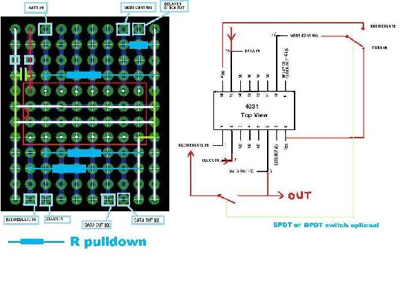
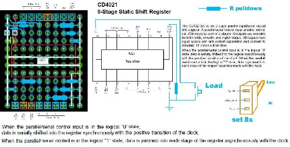
4021 8-stage static shift register |
|
|
It's all in the datasheets, not exactly rocket science. But ok, one more then.
| Description: |
|
| Filesize: |
185.24 KB |
| Viewed: |
1060 Time(s) |
| This image has been reduced to fit the page. Click on it to enlarge. |
|
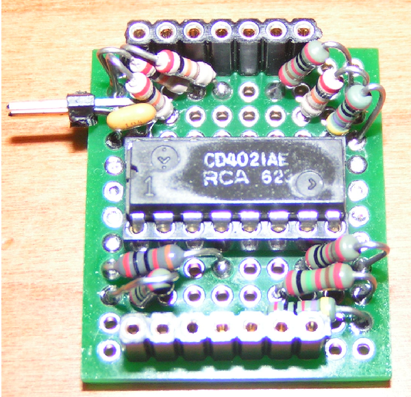
| Description: |
| This is what it looks like. Notice the painstakingly measured matching pulldown resistors :) . Two pulldowns had to share a hole in the upper left corner. |
|
| Filesize: |
2.45 MB |
| Viewed: |
723 Time(s) |
| This image has been reduced to fit the page. Click on it to enlarge. |
|
|
|
|
Back to top
|
|
|
electri-fire
Joined: Jul 26, 2006
Posts: 536
Location: Dordrecht NL
Audio files: 4
G2 patch files: 4
|
| Posted: Tue Feb 23, 2010 5:04 am Post subject:
4031 updated |
|
|
| I had a pulldown on the 4031 drawing that shouldn't have been there. Please reload if applicable. |
|
|
Back to top
|
|
|
electri-fire
Joined: Jul 26, 2006
Posts: 536
Location: Dordrecht NL
Audio files: 4
G2 patch files: 4
|
|
|
Back to top
|
|
|
electri-fire
Joined: Jul 26, 2006
Posts: 536
Location: Dordrecht NL
Audio files: 4
G2 patch files: 4
|
| Posted: Mon Mar 15, 2010 4:15 pm Post subject:
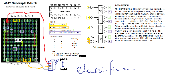
4042 Quad Latch |
|
|
Hey, I discovered these in my collection. The 4042 Quad Latch. What's that you may ask. It has 4 inputs, 4 outputs, 4 inverted outputs.
And two Enable inputs. When both Enable pins are equal, both Hi or both Low the four inputs are passed to the outputs, as is, and inverted.
At the moment the Enable pins are NOT equal, the outputs are held.
With one Enable input fixed to ground (or +V), the other Enable input can function as a single Hold switch.
I laid out a little scheme with a manual Hold switch.
But hey, come to think of it, using both enable pins and the 4 data in pins would take six oscillators. Six oscillators from a 40106 hardwired to the 4042 might be an interesting little module to have.
Edit: E0 to Ground corrected. Now it is actually grounded.
| Description: |
|
| Filesize: |
553.07 KB |
| Viewed: |
922 Time(s) |
| This image has been reduced to fit the page. Click on it to enlarge. |
|
| Description: |
|
Download (listen) |
| Filename: |
4042B - Quadruple D-latch.pdf |
| Filesize: |
63.19 KB |
| Downloaded: |
1511 Time(s) |
Last edited by electri-fire on Mon Mar 15, 2010 4:52 pm; edited 1 time in total |
|
|
Back to top
|
|
|
RF
Joined: Mar 23, 2007
Posts: 1502
Location: Northern Minnesota, USA
Audio files: 28
|
| Posted: Mon Mar 15, 2010 4:22 pm Post subject:
|
|
|
Electri-fire - You have become prodigious and beneficent!
Good stuff - Thanks for sharing!
bruce
_________________
www.sdiy.org/rfeng
"I want to make these sounds that go wooo-wooo-ah-woo-woo.”
(Herb Deutsch to Bob Moog ~1963) |
|
|
Back to top
|
|
|
electri-fire
Joined: Jul 26, 2006
Posts: 536
Location: Dordrecht NL
Audio files: 4
G2 patch files: 4
|
| Posted: Mon Mar 15, 2010 4:41 pm Post subject:
4042 Quad Latch: More Crazy Ideas |
|
|
I should mention: I just made this up, but...
What if I added a R2R DAC (like Inventor used in his 4-Osc-Lunetta schem he posted) at the outputs of the 4042?
Then we would have a 4-bit Control Voltage available to power the 40106 oscillators. Result? Silence, as the 40106 has no power, so no oscillations....
Now have a momentary +V added to pin 16 of the 40106 to start the circuit. Oscillations start, and voltages are held at the (powered) 4042.
Now the 40106 is powered by the varying output of the 4042 R2R DAC.
Output frequency of the 40106 change with varying voltage, thus changing the patterns from the 4042. Those patterns will change the output frequency of the 40106. Next, .....
(electri-fire has just left the room. His manic laughter can be heard as he makes his way up the stairs.)
. |
|
|
Back to top
|
|
|
Inventor
Stream Operator
Joined: Oct 13, 2007
Posts: 6221
Location: near Austin, Tx, USA
Audio files: 267
|
| Posted: Mon Mar 15, 2010 5:37 pm Post subject:
|
|
|
Way cool Mathe, I'm glad your getting good use out of those boards. I'll send you another ten soon as per your request. Keep on truckin'!
Les
_________________
"Let's make noise for peace." - Kijjaz |
|
|
Back to top
|
|
|
jean bender
Joined: Feb 21, 2010
Posts: 139
Location: france
|
| Posted: Thu Mar 18, 2010 8:36 am Post subject:
|
|
|
Hi !!
Very intersting shares ! Thanks for letting us discovering your work !
Could you explain me how you determine pull down resistors values, and why do you use them ??
Thanks !
_________________
http://h.a.k.free.fr/
www.electroncanon.org |
|
|
Back to top
|
|
|
RF
Joined: Mar 23, 2007
Posts: 1502
Location: Northern Minnesota, USA
Audio files: 28
|
| Posted: Thu Mar 18, 2010 8:46 am Post subject:
|
|
|
| deadbeat wrote: |
Could you explain me how you determine pull down resistors values, and why do you use them ??
Thanks ! |
Take a look here......
http://electro-music.com/forum/topic-40754.html
bruce
_________________
www.sdiy.org/rfeng
"I want to make these sounds that go wooo-wooo-ah-woo-woo.”
(Herb Deutsch to Bob Moog ~1963) |
|
|
Back to top
|
|
|
jean bender
Joined: Feb 21, 2010
Posts: 139
Location: france
|
|
|
Back to top
|
|
|
-minus-
Joined: Oct 26, 2008
Posts: 787
Audio files: 13
|
| Posted: Mon Mar 29, 2010 5:06 am Post subject:
|
|
|
Yes, you see... this is IT!!! Hidden away among all the bum-fodder of this topic is some hands on stuff. This is EXACTLY what novices like myself need. Practical examples of what to actually make... what to solder where.
Eventually this elusive information will filter down from the secret society of the Kingdom of Lunetta into the lower caste masses...
Thanks everyone for sharing these designs! More of the same please anyone and everyone! |
|
|
Back to top
|
|
|
RF
Joined: Mar 23, 2007
Posts: 1502
Location: Northern Minnesota, USA
Audio files: 28
|
| Posted: Mon Mar 29, 2010 6:41 am Post subject:
|
|
|
| -minus- wrote: | | ...secret society of the Kingdom of Lunetta |
That's how Mysterians roll! 

I won't speak for everyone - but for me there was a "concept" learning curve. Before mosc began talking about these -not that long ago - there were few sound samples, no drawings, and not much of a community to draw upon. The early posters in the Lunetta forum provided a few ideas to get started, and that's really all there was.
One thing I am amazed by, is the variety of directions people have taken these. Everyone has a unique twist on the way they use them and how they put them together. Very cool.
It's really a different way to think about making music instruments...
Build a few circuits on the breadboard, wire them together and it begins to become more clear..
bruce
_________________
www.sdiy.org/rfeng
"I want to make these sounds that go wooo-wooo-ah-woo-woo.”
(Herb Deutsch to Bob Moog ~1963) |
|
|
Back to top
|
|
|
Rykhaard
Joined: Sep 02, 2007
Posts: 1290
Location: Canada
|
| Posted: Mon Mar 29, 2010 2:28 pm Post subject:
|
|
|
| RF wrote: | | -minus- wrote: | | ...secret society of the Kingdom of Lunetta |
That's how Mysterians roll!
I won't speak for everyone - but for me there was a "concept" learning curve. Before mosc began talking about these -not that long ago - there were few sound samples, no drawings, and not much of a community to draw upon. The early posters in the Lunetta forum provided a few ideas to get started, and that's really all there was.
One thing I am amazed by, is the variety of directions people have taken these. Everyone has a unique twist on the way they use them and how they put them together. Very cool.
It's really a different way to think about making music instruments...
Build a few circuits on the breadboard, wire them together and it begins to become more clear..
bruce |
I agree on everything from Bruce, in my experiences here.
As well - I see the Lunetta existance as well (myself specifically, I should limit) as a 'new' (old way found again) way of making music - in many regards, throwing away the restrictions that are and have been cast upon those of us who've had lessons, as well as others who aren't happy with popular radio; etc. (Many more angles to this.)
What has been growing from this, especially thanks to Howard and Stanley Lunetta - are the avenues opened to us to return, to this area and create things that please us.
/stepping down from pedestal, instead of continuing on for a world record attempt in speech giving  
Dada |
|
|
Back to top
|
|
|
DGTom

Joined: Dec 08, 2008
Posts: 211
Location: Adelaide
Audio files: 3
G2 patch files: 1
|
| Posted: Mon Mar 29, 2010 6:31 pm Post subject:
|
|
|
bum-fodder? elusive information? How much have you actually bothered to read? How much time have you bothered to spend messing with ICs on a breadboard?
For me the Lunetta spirit is experimentation & investigation - just wire the IC pins to connectors of some sort & get connecting... how is that arcane knowledge!?
Anyway;
some great ideas here electri-fire, I think it really proves you can make some great stuff with pretty much any chips you have on hand when you approach them in a creative / explorative way  |
|
|
Back to top
|
|
|
RF
Joined: Mar 23, 2007
Posts: 1502
Location: Northern Minnesota, USA
Audio files: 28
|
| Posted: Mon Mar 29, 2010 8:01 pm Post subject:
|
|
|
| DGTom wrote: | bum-fodder? elusive information? How much have you actually bothered to read? How much time have you bothered to spend messing with ICs on a breadboard?
|
I nominate DGTom as Lune-Diplomat to the world. 
_________________
www.sdiy.org/rfeng
"I want to make these sounds that go wooo-wooo-ah-woo-woo.”
(Herb Deutsch to Bob Moog ~1963) |
|
|
Back to top
|
|
|
electri-fire
Joined: Jul 26, 2006
Posts: 536
Location: Dordrecht NL
Audio files: 4
G2 patch files: 4
|
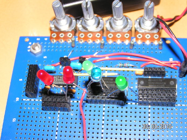
| Posted: Tue Mar 30, 2010 3:02 pm Post subject:
Use of multiple in/out's with Mickey Mouse Logic LED's |
|
|
So I built these one-chip modules, and droffset asked me in the chatroom recently how I get these organized. I had to admit I had these on the lap, pots, wires and batteries dangling all over the place.
Inspired by droffset's latest build, I decided to go a similar route, building a No-Frontplate-Lunetta, that can host my CMOS modules and have some generic stuff hardwired on board.
I mentioned wanting multiple out's, wich I have indeed, and they are great fun.
This being the design section, not the Show-Your-Lunetta thread, here's an interesting observation. You may have heard of Mickey Mouse Logic:
http://www.musicfromouterspace.com/analogsynth/mmlogic.html
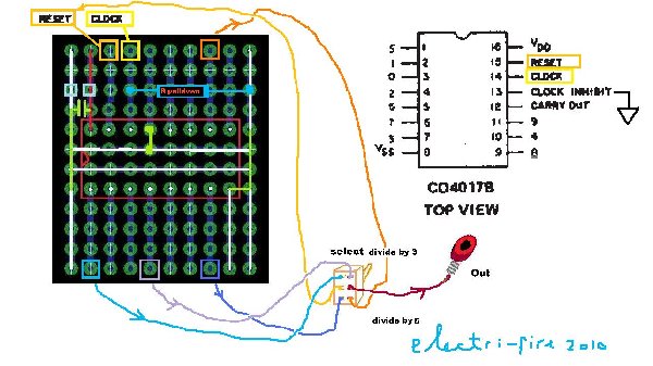
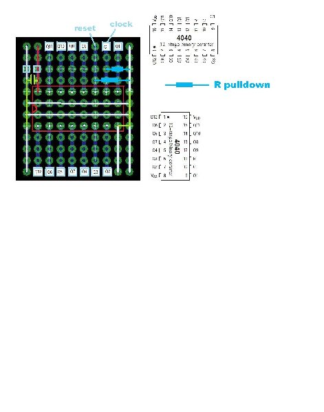
I have a 40106 with 4 osc's, two of them hardwired to 4040's.
Playing around with LED's between random outputs (three of each) and picking of the sound from the LED's intermodulates the frequencies nicely. With multiple LED's, the sounds are different from each LED lead, but obviously rhythmically related. Nice for stereo. I'm starting to wonder why I'd even bother with this Gate stuff at all.
I will definitely add more output headers to accommodate interconnections with LED's. Maybe I best make an array of LED's near the in/out headers, some of my LED leads are too thick for the in/outputs, and having different color LED's is fun. Also my LED leads are bent all over the place now, and have to be forced in.
All LED's would need double (ah, make that triple) header in-out's to be able to send the sound to my mixer (a TL062, chosen for it's low power use).
This setup beats any rude words out of my CMOS Gate modules. It's fast and versatile, cheap, needs little space on the board, is easy to build, and could replace your fixed LED's.
electri-fire says: Recommendable.
| Description: |
|
| Filesize: |
682.56 KB |
| Viewed: |
633 Time(s) |
| This image has been reduced to fit the page. Click on it to enlarge. |
|
|
|
|
Back to top
|
|
|
droffset
Joined: Feb 02, 2009
Posts: 515
Location: London area
Audio files: 2
|
| Posted: Tue Mar 30, 2010 7:51 pm Post subject:
|
|
|
Cool that you're using the LEDs that way. So the 1 or 0 value at each side of the LED is doing its own gating? Pretty sweet.
Multiple outs is a good idea, I've had to splice together Y-splitter cables to get mults.
EDIT
Posting this image in this thread to show how I did the overall design for mine.

_________________
==================
Check out the FREE Intro to Lunettas Document
https://docs.google.com/document/d/1V9qerry_PsXTZqt_UDx7C-wcuMe_6_gyy6M_MyAgQoA/edit?usp=sharing
Edit: Spelling mistakes. |
|
|
Back to top
|
|
|
electri-fire
Joined: Jul 26, 2006
Posts: 536
Location: Dordrecht NL
Audio files: 4
G2 patch files: 4
|
| Posted: Wed Mar 31, 2010 9:19 am Post subject:
|
|
|
| droffset wrote: | | So the 1 or 0 value at each side of the LED is doing its own gating? Pretty sweet. |
Exactly. All connections are made between outputs. I have 5 LED's in the posted picture with some leads sharing an output. So there's seven different sounds going on there. Doing this with gates takes two IC's at least.
I figured a bunch of patchable LED's might benefit from multiple in-out's but there's no need for that. As the LED leads are plugged into CMOS outputs I better make more of those.
Hmpff, I never seem to make up a layout and actually pursue finishing it as planned. I had already soldered part of a potmeter assembly consisting of 8 trimpots. These will have DIP switches to switch them in series. The wiper will have two inputs, straight, one through a resistor.
The idea is to have this configurable as single pots, adjustable R/xR DAC's, and whatever comes to mind later, probably disrupting any conceptions of what it should be able to do later : : . : .
So between this row of trimpots I had room planned for three E-chuck-Lunetta boards, but that's not going to happen. My little mixer is screaming for more inputs. I had 8 Normally Open Momentary to +V, plus one "engage switch" planned, for use with a 4021 shift register and 4042 S&H module, but eventually wising up I'll refrain from soldering them up for now.
I think this will have to be a relatively low chipcount Lunetta. |
|
|
Back to top
|
|
|
|

 Forum index » DIY Hardware and Software » Lunettas - circuits inspired by Stanley Lunetta