| Author |
Message |
Ricko
Joined: Dec 25, 2007
Posts: 251
Location: Sydney, Australia
Audio files: 27
|
 Posted: Wed Apr 08, 2009 8:59 pm Post subject:
The Extractorator: sync, freq, synced saw + servo Posted: Wed Apr 08, 2009 8:59 pm Post subject:
The Extractorator: sync, freq, synced saw + servo |
  |
|
I have been thinking about better ways to integrate digital and analog synths. In part this is because the digital gives such accurate control of
scales, but also because I have wanted to explore cheaper ways of getting
MIDI-to-CV: something where multiple units were affordable.
Here is what I have been playing around with. The Extractorator is (simulated in SPICE, not built yet) a linear frequency to voltage converter with a sawtooth VCO synced to the input.
The output of the VCO always exactly tracks the input oscillator, so the synth can be tuned exactly. (The system is similar to the analog oscillators of the Roland JX-3P. ) The linear CV is not intended for
high accuracy driving VCOs, however a servo configuration is possible (see below.)
Bob Moog's patented Peak Picker is used to provide input-level independence and should be capable of handling many more input
waveshapes than other systems (since it won't latch onto higher higher
harmonics from multiple zero-crossings.)
Because of the syncing and intended use, there is no sample and hold mechanism: no input, the output of the VCO will freewheel at some slow rate. The use of the sync mechanism means that slow tracking response will not show up as glide, but as a slight attack (for any new notes and notes that are higher than the previous, since the integrator won't have reached 5V before resetting) and as a sync sweep (for notes that are lower than the previous) as the VCO slows down.
Here are the kinds of use cases I had in mind:
1) A slave waveshaper from an analog VCO, rather like the ARP 2500 sawtooth slave.
2) An instrument or voice tracker. A companion envelope follower
would be needed.
3) A tracker for a MIDI synth. For example, the old yamaha FB-01 has a right and left output. The right output could be sent to an envelope follower to provide dynamics and trigger; the left output, with much more legato decay times, would be sent to an Extractorator for pitch extraction. This overcomes the typical problem of instability with stacatto passages.
4) A servo configuation with two extractorators, allowing feedback correction of the frequency voltage. In this situation, Extractorator 1 is driving an independent VCO which feeds into Extractorator 2. The pitch from extractorator 2 is compared to the pitch from extractorator 1, and the CV into the VCO is adjusted by the difference.
Anyway, I hope this is of interest to someone. There is some scope for tweaks; different values to cope with extreme bass better. Probably useful to add a log converter to drive expo synth modules better.
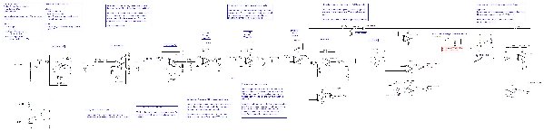
| Description: |
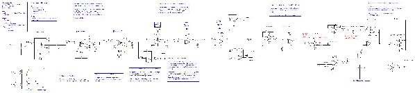
| Schematic (TI-SPEC) of The Extractorator |
|
| Filesize: |
507.64 KB |
| Viewed: |
758 Time(s) |
| This image has been reduced to fit the page. Click on it to enlarge. |
|
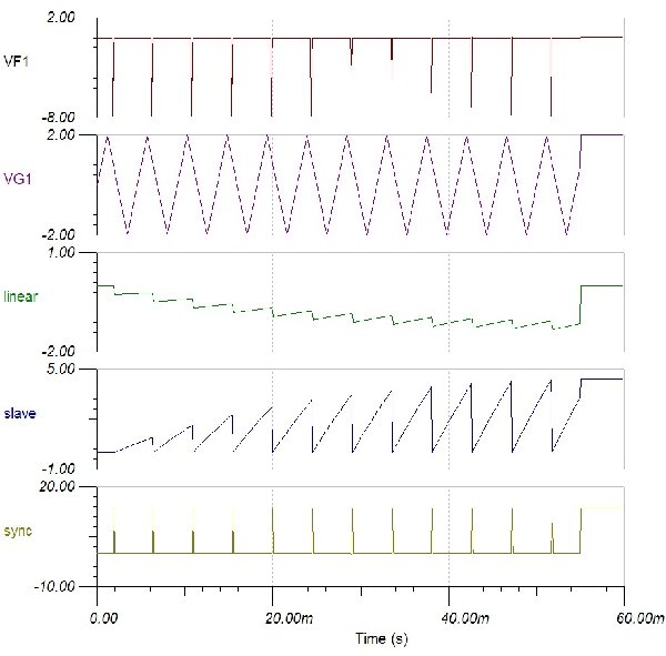
| Description: |
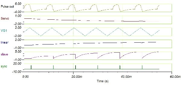
| Response of extractorator at 220k input signal. Note the fade-in effect for the first few cycles until it stabilizes. |
|
| Filesize: |
109.54 KB |
| Viewed: |
380 Time(s) |
| This image has been reduced to fit the page. Click on it to enlarge. |
|
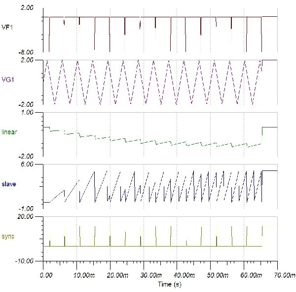
| Description: |
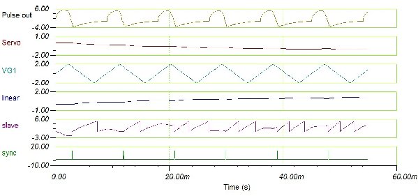
Response of extractorator at 220k input signal. Note the fade-in effect for the first few cycles until it stabilizes.
In this case, the VCO frequency is set higher, so that the output is approximately a saw at twice the input frequency, |
|
| Filesize: |
136.96 KB |
| Viewed: |
375 Time(s) |
| This image has been reduced to fit the page. Click on it to enlarge. |
|
|
|
|
Back to top
|
|
 |
loss1234

Joined: Jul 24, 2007
Posts: 1536
Location: nyc
Audio files: 41
|
|
|
Back to top
|
|
|
Ricko
Joined: Dec 25, 2007
Posts: 251
Location: Sydney, Australia
Audio files: 27
|
| Posted: Wed Apr 08, 2009 10:38 pm Post subject:
|
|
|
It can be built and tested in left to right order (peak pickers, triggers, smoothers, VCO): there is no feedback or other dependencies. The VCO can be tested independently of the sync/pitch in as well.
(I see that the schematic I posted seems to have an inverted linear CV out: so a (scaling, filtering) inverter rather than the voltage follower there would presumably be more useful. Sometime I'll amend the schematic for this: an earlier version I had had pretty good linearity actually, but the design is for a CV good enough for VCFs not for VCOs.)
Cheers
Rick |
|
|
Back to top
|
|
|
Ricko
Joined: Dec 25, 2007
Posts: 251
Location: Sydney, Australia
Audio files: 27
|
| Posted: Fri Apr 10, 2009 8:17 am Post subject:
Update |
|
|
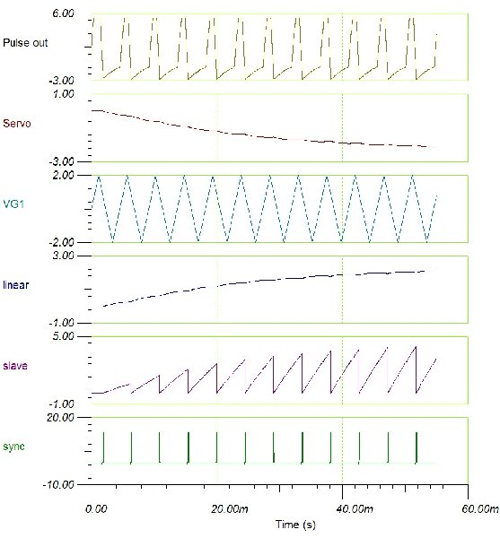
Here is an updated version, with better outputs (better levels, better scale, better smoothing.)
I've added an extra output so that it could be built with 4 TL084s: 1 for peak pickers, 1 for triggers, 1 for integrators and 1 for the VCO.
| Description: |
| Outputs with input signal at 200Hz |
|
| Filesize: |
130.21 KB |
| Viewed: |
441 Time(s) |
| This image has been reduced to fit the page. Click on it to enlarge. |
|
| Description: |
|
| Filesize: |
560.48 KB |
| Viewed: |
639 Time(s) |
| This image has been reduced to fit the page. Click on it to enlarge. |
|
Last edited by Ricko on Fri Apr 10, 2009 10:40 am; edited 1 time in total |
|
|
Back to top
|
|
|
loss1234
Joined: Jul 24, 2007
Posts: 1536
Location: nyc
Audio files: 41
|
|
|
Back to top
|
|
|
loss1234
Joined: Jul 24, 2007
Posts: 1536
Location: nyc
Audio files: 41
|
|
|
Back to top
|
|
|
Ricko
Joined: Dec 25, 2007
Posts: 251
Location: Sydney, Australia
Audio files: 27
|
| Posted: Fri Apr 10, 2009 10:47 am Post subject:
|
|
|
Sorry I must have been updating just as you looked at the post. The update is there now.
One optional value add is that with a resistor and a three-way switch (the two switches in the post) we can get a couple of different waveshapes easily.
Feeding the sawtooth output to the VCO input, we get a slight FM or phase modulation effect that produces a curved sawtooth.
Feeding Peak Picker 2 to the VCO input, and we get a a kind of disrupted shape. (Actually, this will depend on the audio input frequency too.)
Example waveshapes attached.
| Description: |
|
| Filesize: |
101.18 KB |
| Viewed: |
427 Time(s) |
| This image has been reduced to fit the page. Click on it to enlarge. |
|
| Description: |
| Select disrupted wave has interesting interactions with the sync: many different waveshapes that could not be obtained otherwise. |
|
| Filesize: |
103.81 KB |
| Viewed: |
383 Time(s) |
| This image has been reduced to fit the page. Click on it to enlarge. |
|
|
|
|
Back to top
|
|
|
loss1234
Joined: Jul 24, 2007
Posts: 1536
Location: nyc
Audio files: 41
|
|
|
Back to top
|
|
|
Ricko
Joined: Dec 25, 2007
Posts: 251
Location: Sydney, Australia
Audio files: 27
|
| Posted: Fri Apr 10, 2009 6:09 pm Post subject:
|
|
|
Just SPICE.
I've thought about a PCB, but no plans until I've built one on experimenters' board and added log converter.
To print on PC, save to disk, then open in Accessories>Paint. It will print to multiple pages. |
|
|
Back to top
|
|
|
loss1234
Joined: Jul 24, 2007
Posts: 1536
Location: nyc
Audio files: 41
|
|
|
Back to top
|
|
|
loss1234
Joined: Jul 24, 2007
Posts: 1536
Location: nyc
Audio files: 41
|
| Posted: Fri Apr 10, 2009 9:06 pm Post subject:
|
|
|
ok i have some questions now that i have printed it
1. could the opamp schmidt triggers be replaced with 40106's? still keeping the same caps, resistors and diodes after them?
2. are all these triggers turning the signal into a series of fast pulses?
3 am i correct in thinking you then get a linear voltage simply by filtering?
4. R27...what is it doing?
5. also.. i noticed the out of the pulse connects to the saw area...why? do you get a saw by mixing a tri and a pulse or something?
thanks
_________________
-------------------------------------------- check out various dan music at: http://www.myspace.com/lossnyc
http://www.myspace.com/snazelle
http://www.soundclick.com/lossnyc.htm http://www.indie911.com/dan-snazelle |
|
|
Back to top
|
|
|
loss1234
Joined: Jul 24, 2007
Posts: 1536
Location: nyc
Audio files: 41
|
|
|
Back to top
|
|
|
Ricko
Joined: Dec 25, 2007
Posts: 251
Location: Sydney, Australia
Audio files: 27
|
| Posted: Sat Apr 11, 2009 12:51 am Post subject:
Theory of operation |
|
|
The schematics already have quite a lot of notes, but here are some additional ones.
A typical pitch detector or frequency-to-voltage extractor will typically include the following:
1) circuit to detect crossings
2) circuit to generate fixed width pulse
3) circuit to integrate pulses to linear CV
4) circuit to smooth CV
5) circuit to converter from linear to log (for connection with normal synths)
6) circuit for maintaining CV when input disappears.
The Extractorator has 1) to 4) of these currently.
1) Rather than just detecting zero crossings, we try to detect peaks (or near the peaks).
A series of threee Moog "Peak Picker" circuit is used. The wave is first stripped of DC by an RC fileter to center it. Then this goes into a half-wave rectifier so that only the positive portion of the input wave is used. This wave is sent to another peak picker which results in a wave with just the top-half of the incoming wave. Then the third peak picker results in a wave with only the top 1/4 of the original wave.
This is level independent and will generate nice single-crossing waves even with incoming waves that are messy for the other 3/8s of the wave heigher. See the Moog patent for more details and diagrams. The circuit values in the Moog patent seem entirely wrong.
This output is also available as "pulse out", which can be used as an audio waveshape.
2) Normally a one-shot monostable is used to generate fixed width waveshape. Because of the design constraint of using no specialist components, I use a series of pulse generators/schmitt triggers. But the third one, the pulse is fixed width enough to be useful. (The schmidt triggers could indeed be replaced with e.g. 40106, but the remainder of the circuit in particular R35 and R40 may need to be adjusted to suit.)
The width of this pulse determines the maximum frequency that can be detected reliably.
This output is available as "sync out" which can be used to syncronize external oscillators or drive clocks.
3) The integration circuitry is very typical. The response time is perhaps a little fast, giving quite staircase output, however, this is suitable for driving the VCO.
A fast integration time also limits the performance on lower notes; however a slow integration time will be more audible introduce more glide effects.
4) A final smoothing is done by c27. A larger one may be better for bass.
The highest and lowest frequencies of the CV out are more limited than the sync.
The output is scaled to 10V/kHz. So 100 Hz input will be 1V output. 200 Hx input will be 2V. 1kHz input will be 10V output.
5) Currently there is no log converter, which would be required to drive conventional VCOs. However, perfect tracking for VCOs has not been a design constraint. The tracking is good enough for VCFs though.
6) No sample-and-hold or other mechanism has been provided. This is because the intended use is in conjunction with an envelope follower on another channel.
The VCO is a conventional sawtooth oscillator, inspired by a Ray Wilson circuit. The synch mechanism with dual FETs is undoubtedly over-engineered here, and I guess could be simplified.
U11 et al is an integrator that charges up at a rate determined by the voltage from U16. U15 is a Schmitt trigger that usually outputs -15 but puts out +15 when the input signal crosses the 5V threshold set by voltage divider r38, r39. It opens the FETs and discharges the integrator cap c19. resetting the VCO.
However, in usual operation, a sync signal from stage 2) will also reset the sawtooth. If P3+r40 is around 500K, then the incoming synch pulse will occur before the saw has reached 5V threshold. If P3 is less than this, the VCOs own reset circuitry will operate, and a synced saw effect will occur.
Because the VCO is linear, it has no need for any temperature compensation circuitry.
The VCO also has an optional section for different waveshapes. This would typically be a three position switch, one not connected, one connected to the saw output, and one to the pulse output. A 2M resistor seems to provide a useful amount of modulation. This provides a kind of phase modulation, distorting the waveshape in to either a curve (from the saw output) or a complex wave (from the pulse in waveshape.) |
|
|
Back to top
|
|
|
Ricko
Joined: Dec 25, 2007
Posts: 251
Location: Sydney, Australia
Audio files: 27
|
| Posted: Sat Apr 11, 2009 1:04 am Post subject:
|
|
|
| loss1234 wrote: | ok i have some questions now that i have printed it
1. could the opamp schmidt triggers be replaced with 40106's? still keeping the same caps, resistors and diodes after them?
2. are all these triggers turning the signal into a series of fast pulses?
3 am i correct in thinking you then get a linear voltage simply by filtering?
4. R27...what is it doing?
5. also.. i noticed the out of the pulse connects to the saw area...why? do you get a saw by mixing a tri and a pulse or something?
thanks |
1. Yes. Pulses of the equivalent width would be generated. But the height may differ. in which case the r36 and r40/P3 values would have to be scaled proportionately too.
2. Yes. Small constant-width pulse.
(...of less than 1/12000s which is 50% pulse width at 6kHz, the minimum max freq I wanted to support.)
3. Yes.
4. I am not a FET expert. My guess is some kind of current limiting for the FET, I just copied it.
5. Very small amount of FM. It bends the waveshape and only costs a resistor and a few switches. It is just a little value-add to make the VCO more interesting, it is not necessary for normal operation. For normal saw operation, R50 would be disconnected from any signal. The circuit diagram is not clear, but there are two switches connected in series to r50: one disconnects R50 from any input, the other selects two different inputs, so they can be replaced by a three-way switch. (SPICE didn't have such a component so I had to use two switches.) |
|
|
Back to top
|
|
|
loss1234
Joined: Jul 24, 2007
Posts: 1536
Location: nyc
Audio files: 41
|
| Posted: Sat Apr 11, 2009 7:42 am Post subject:
|
|
|
thanks a lot!
i am saddened that i havent had the time to build it yet
my only worry is that if it is putting out 10v per khz instead of the usual 1v/khz, that it might fry my filter. wouldnt that mean it could put out 50 volts for 5khz??
or am i mistaken? could i just stick an expo converter on the cv out? or is it more complicated an issue
i wonder if moog put the wrong values on the patent on purpose??
lots of great stuff here
_________________
-------------------------------------------- check out various dan music at: http://www.myspace.com/lossnyc
http://www.myspace.com/snazelle
http://www.soundclick.com/lossnyc.htm http://www.indie911.com/dan-snazelle |
|
|
Back to top
|
|
|
Ricko
Joined: Dec 25, 2007
Posts: 251
Location: Sydney, Australia
Audio files: 27
|
| Posted: Sun Apr 12, 2009 1:16 am Post subject:
|
|
|
To get 1V/kHz change R34 to 220k. I did that originally then, changed, because CV tracking is poor above 1k, but probably 1V/kHz is indeed better, so I'll change back to 1V/kHz.
It won't output 50V and fry anything, because it only runs on 15V power. |
|
|
Back to top
|
|
|
loss1234
Joined: Jul 24, 2007
Posts: 1536
Location: nyc
Audio files: 41
|
|
|
Back to top
|
|
|
Ricko
Joined: Dec 25, 2007
Posts: 251
Location: Sydney, Australia
Audio files: 27
|
| Posted: Thu Jul 02, 2009 7:15 am Post subject:
|
|
|
I just sighted the design for the Roland guitar synth GR-300. My brother used to have one. Great site:
http://www.joness.com/gr300/patent.htm
It has several really interesting features that make it pretty different from the general pipeline I wrote about above. Probably old hat for everyone else.
It seems to have two big design decisions.
The first is that appar2ently the big problem with guitar is that the first or second harmonic can be louder than the fundamental during the duration of the note, causing an octave flip and unwanted volume boost. So the signals from each string first go through a band pass filter that has a simple tracking mechanism (it flips between a lower and higher frequency, it seems) to boost the fundamental. There is also a volume gating arrangement.
The second design decision is to have a waveshape that changes up and down the fretboard. The slope of the saw is constant and rather than allowing lower notes to get louder as the saw grows more, the wave is clipped. So it looks like a squared saw. This removes complexity from the circuit but also has the nice effect that the tone of a note in one position will be different than the tone of the same note in a different position, just like a guitar.
In other news about pitch followers, the sonuus looks pretty interesting:
http://www.sonuus.com/products.html |
|
|
Back to top
|
|
|
j.dilisio

Joined: May 19, 2009
Posts: 200
Location: baltimore
|
| Posted: Mon Aug 03, 2009 9:31 am Post subject:
|
|
|
I've been looking for a good pitch to voltage converter for a while now. The only one's I've found are from old synth books from the 70's that probably don't work that great.
I'm excited to hear how well this works.
Are you planning on adding an envelope follower as well? |
|
|
Back to top
|
|
|
StephenGiles
Joined: Apr 17, 2006
Posts: 507
Location: England
|
| Posted: Fri Oct 09, 2009 1:31 am Post subject:
|
|
|
| j.dilisio wrote: | I've been looking for a good pitch to voltage converter for a while now. The only one's I've found are from old synth books from the 70's that probably don't work that great.
I'm excited to hear how well this works.
Are you planning on adding an envelope follower as well? |
Any new on an envelope follower? |
|
|
Back to top
|
|
|
Ricko
Joined: Dec 25, 2007
Posts: 251
Location: Sydney, Australia
Audio files: 27
|
| Posted: Mon Oct 12, 2009 9:57 pm Post subject:
|
|
|
| For an envelope follower, I posted some redrawn schematics of the Buchla 230 on this list. There does not seem that much variation in EFs apart from the Buchla: some have different cap values or higher order filters, and for good bass following you need a fullwave rectifier before the EF. |
|
|
Back to top
|
|
|
|

 Forum index » DIY Hardware and Software

