| Author |
Message |
petegaggs
Joined: Jan 04, 2018
Posts: 23
Location: Cambridge, UK
Audio files: 1
|
 Posted: Sat Jan 20, 2018 8:36 am Post subject:
Arduino controlled oscillator Posted: Sat Jan 20, 2018 8:36 am Post subject:
Arduino controlled oscillator
Subject description: analogue sawtooth oscillator, with MIDI control |
  |
|
Here is my latest project. It's an oscillator controlled by an arduino.
This is a novel approach - it's a hybrid design, with a standard op-amp integrator to generate a sawtooth much like other analogue oscillator designs.
However, the reset of the integrator comes from the microcontroller, this avoids needing any tempco, matched pairs, calibration etc.
I use the 16 bit timer to generate a square wave of the correct frequency. The rising edge of this will reset the integrator.
So as well as a sawtooth, there is a square wave available as well, I'm not using this yet. If I were to use this, I would suggest buffering with an opamp before taking it off-board.
The integrator drive comes from an SPI DAC. The exponential conversion is done in software by lookup table. The integrator drive level does not need to be precise, any error here will result in a small change of amplitude of the sawtooth, rather than a frequency error, which would be the case with traditional oscillator circuits.
The sawtooth is about 4V pk-pk, and the design works over a 7 octave range.
Other features:
MIDI control
powered from +9V supply (I have a local inverter to generate -9V for the op-amp).
Nice an simple, not too many parts.
I used an Arduino nano in my prototype, since that was what I had to hand, but it was originally going to be a pro mini 5V 16MHz.
Note that you need the arduino MIDI library installed. Also the timer is used directly, so it won't work on all Arduinos. It will work on any '328p based hardware.
source code and other stuff is here:
https://github.com/petegaggs/MIDI-controlled-oscillator
| Description: |
|
| Filesize: |
974.01 KB |
| Viewed: |
995 Time(s) |
| This image has been reduced to fit the page. Click on it to enlarge. |
|
| Description: |
|

Download (listen) |
| Filename: |
MIDI-controlled-oscillator.pdf |
| Filesize: |
54.1 KB |
| Downloaded: |
1280 Time(s) |
|
|
|
Back to top
|
|
 |
Cynosure
Site Admin

Joined: Dec 11, 2010
Posts: 1025
Location: Toronto, Ontario - Canada
Audio files: 82
|
| Posted: Sat Jan 20, 2018 8:48 pm Post subject:
|
|
|
Cool. I have been meaning to test this for a while, but I never got around to it. From the sounds of it, what you have created is actually a DCO. You should also adjust the voltage so that the higher frequencies do not have a lower amplitude.
_________________
JacobWatters.com |
|
|
Back to top
|
|
|
Grumble
Joined: Nov 23, 2015
Posts: 1320
Location: Netherlands
Audio files: 30
|
| Posted: Sun Jan 21, 2018 4:54 am Post subject:
|
|
|
In the low frequencies I don't see any problems, but how accurate is it in the higher audio range?
_________________
my synth |
|
|
Back to top
|
|
|
petegaggs
Joined: Jan 04, 2018
Posts: 23
Location: Cambridge, UK
Audio files: 1
|
| Posted: Sun Jan 21, 2018 5:53 am Post subject:
|
|
|
| Cynosure wrote: | | You should also adjust the voltage so that the higher frequencies do not have a lower amplitude. |
That's actually what happens, there are 2 lookup tables, one for timer to get the frequency, one one for the SPI DAC that sets the integrator drive.
The DAC voltage is about 30mV at the bottom end (midi note 21) rising to 5V at the top (midi note 108).
There's a spreadsheet in the github repository showing how it's all worked out. |
|
|
Back to top
|
|
|
petegaggs
Joined: Jan 04, 2018
Posts: 23
Location: Cambridge, UK
Audio files: 1
|
| Posted: Sun Jan 21, 2018 6:05 am Post subject:
|
|
|
| Grumble wrote: | | In the low frequencies I don't see any problems, but how accurate is it in the higher audio range? |
You're right, it does get less accurate for higher frequencies, but it's still OK.
the highest note is note 108, corresponding to 4186Hz, here the timer value is 239 decimal, so the precision of the timer is about 0.5% at this point. |
|
|
Back to top
|
|
|
Cynosure
Site Admin
Joined: Dec 11, 2010
Posts: 1025
Location: Toronto, Ontario - Canada
Audio files: 82
|
| Posted: Sun Jan 21, 2018 9:45 am Post subject:
|
|
|
Very cool 
_________________
JacobWatters.com |
|
|
Back to top
|
|
|
petegaggs
Joined: Jan 04, 2018
Posts: 23
Location: Cambridge, UK
Audio files: 1
|
| Posted: Sun Jan 21, 2018 2:20 pm Post subject:
|
|
|
| Cynosure wrote: | | Very cool |
thanks! |
|
|
Back to top
|
|
|
Grumble
Joined: Nov 23, 2015
Posts: 1320
Location: Netherlands
Audio files: 30
|
| Posted: Sun Jan 21, 2018 2:38 pm Post subject:
|
|
|
very nice project! 
_________________
my synth |
|
|
Back to top
|
|
|
LFLab
Joined: Dec 17, 2009
Posts: 497
Location: Rosmalen, Netherlands
|
| Posted: Mon Jan 22, 2018 3:50 am Post subject:
|
|
|
| Nice, so a DCO? Interesting! |
|
|
Back to top
|
|
|
Grumble
Joined: Nov 23, 2015
Posts: 1320
Location: Netherlands
Audio files: 30
|
| Posted: Mon Jan 22, 2018 3:12 pm Post subject:
|
|
|
it’s a new breed: DCAO (digital controlled analog oscillator)
Drawback is that it plays a fixed maximum number of frequencies, due to the limit of the size of the two lookup tables.
Maybe it is possible to have the Arduino calculate the two values, or is it getting to slow doing it like this?
_________________
my synth |
|
|
Back to top
|
|
|
Sebo

Joined: Apr 27, 2007
Posts: 564
Location: Argentina
|
|
|
Back to top
|
|
|
petegaggs
Joined: Jan 04, 2018
Posts: 23
Location: Cambridge, UK
Audio files: 1
|
| Posted: Mon Feb 12, 2018 10:58 am Post subject:
|
|
|
| Grumble wrote: |
Maybe it is possible to have the Arduino calculate the two values, or is it getting to slow doing it like this? |
I was thinking about that, I think it should be possible to calculate it on the fly, I might to try adapt it to voltage control using the ADC |
|
|
Back to top
|
|
|
petegaggs
Joined: Jan 04, 2018
Posts: 23
Location: Cambridge, UK
Audio files: 1
|
| Posted: Mon Feb 12, 2018 11:19 am Post subject:
|
|
|
Interesting, it does seem to be essentially the same thing |
|
|
Back to top
|
|
|
petegaggs
Joined: Jan 04, 2018
Posts: 23
Location: Cambridge, UK
Audio files: 1
|
|
|
Back to top
|
|
|
Sebo
Joined: Apr 27, 2007
Posts: 564
Location: Argentina
|
| Posted: Fri Feb 16, 2018 10:40 am Post subject:
|
|
|
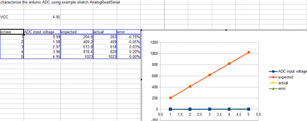
I did several modules in Arduino using it's ADCs as 1V/Oct input and I could get 5 octaves of decent tracking... Always using look up tables.
_________________
Sebo
---------------------------------------
My Music:
https://www.facebook.com/cosaquitos/ |
|
|
Back to top
|
|
|
Grumble
Joined: Nov 23, 2015
Posts: 1320
Location: Netherlands
Audio files: 30
|
| Posted: Fri Feb 16, 2018 12:12 pm Post subject:
|
|
|
How do you use tables and still implement pitch-shift?
_________________
my synth |
|
|
Back to top
|
|
|
Sebo
Joined: Apr 27, 2007
Posts: 564
Location: Argentina
|
| Posted: Fri Feb 16, 2018 1:44 pm Post subject:
|
|
|
I interpolate the tables...
_________________
Sebo
---------------------------------------
My Music:
https://www.facebook.com/cosaquitos/ |
|
|
Back to top
|
|
|
petegaggs
Joined: Jan 04, 2018
Posts: 23
Location: Cambridge, UK
Audio files: 1
|
|
|
Back to top
|
|
|
synthjakk
Joined: Feb 12, 2018
Posts: 20
Location: UK
|
| Posted: Tue Mar 13, 2018 9:19 am Post subject:
|
|
|
This is exactly the kind of project that I want to try. Apologies if this is a stupid question, what is the purpose of the LMC7660INNOPB Voltage converter? and why is'nt it or the 78LO5 connected to the rest of the circuit?
I have ordered the parts and want to build this project as a learning experience! Any update on the gate implementation? |
|
|
Back to top
|
|
|
petegaggs
Joined: Jan 04, 2018
Posts: 23
Location: Cambridge, UK
Audio files: 1
|
| Posted: Tue Mar 13, 2018 11:27 am Post subject:
|
|
|
| synthjakk wrote: | This is exactly the kind of project that I want to try. Apologies if this is a stupid question, what is the purpose of the LMC7660INNOPB Voltage converter? and why is'nt it or the 78LO5 connected to the rest of the circuit?
I have ordered the parts and want to build this project as a learning experience! Any update on the gate implementation? |
Hi synthjakk,
The 7660 is used to generate a -9V supply from a +9V supply.
I used it because I wanted to power the whole thing from a single 9V supply. If you already have a negative supply rail available, you can leave this and the associated parts out.
I included a 7805 regulator to provide 5V power supply, this is needed by the arduino, the DAC and a few other things. As I've drawn it, this is providing 5V power in to the VCC pin of the arduino. Alternatively, you can connect 9V to the RAW pin of the arduino and the arduino's built in regulator will give 5V out instead (the VCC pin can be input or output). Ensure you do one or the other not both.
For the GATE output, the software is already driving it, I would suggest including a 1k series resistor and connect it to a socket to drive an envelope generator.
I hope your build goes well. |
|
|
Back to top
|
|
|
synthjakk
Joined: Feb 12, 2018
Posts: 20
Location: UK
|
| Posted: Fri Mar 16, 2018 12:59 pm Post subject:
|
|
|
Ahh I see, that makes A lot more sense! Regarding the code, you mention that the value 0.97783686 is in the attached spread sheet, however I can't seem to find this value anywhere. What is its purpose?
Also, what does the 1000000.0 and the -1 represent here?
uint16_t timerSetting = round((1000000.0 / freqHz)-1.0);
My parts arrived today so I will upload a video once it is all working properly! I want to try and fully understand the code to help comprehend the project |
|
|
Back to top
|
|
|
petegaggs
Joined: Jan 04, 2018
Posts: 23
Location: Cambridge, UK
Audio files: 1
|
| Posted: Fri Mar 16, 2018 2:35 pm Post subject:
|
|
|
>Regarding the code, you mention that the value 0.97783686 is in the attached spread sheet, however I can't seem to find this value anywhere. What is its purpose?
Sorry, I forgot to update the spreadsheet after my last changes, it's there in the git repository now. So originally, I worked out the values for timer and DAC in advance in a spreadsheet for each midi note. This is now changed so the arduino software calculates them itself (in function updateNotePitch), this allows analogue voltage control to be used, and pitch bend.
If you look at the sheet called 'voltage control' you'll see how it works. The constant DAC_MULTIPLIER is a function of
a) desired ramp peak voltage
b) integrator R
c) integrator C
d) DAC bit resolution
e) DAC full scale voltage
TBH, it doesn't really need to be a precise value, 1.0 would probably have been close enough, and would have saved a few cycles, however having this constant does allow the above parameters to be changed about.
>Also, what does the 1000000.0 and the -1 represent here?
uint16_t timerSetting = round((1000000.0 / freqHz)-1.0);
We have to multiply by one million because freqHz is a floating point number representing the frequency in Hz, and the timer value is effectively in microseconds (the timer is actually running at 2MHz, and the timer period is half the note period)
The -1 is needed because the timer is zero indexed, e.g. loading it with a value of 0 will make the timer run for 1 x timer clock, so to make it exactly right the timer is loaded with the note period in microseconds, minus one.
I look forward to hearing your results! |
|
|
Back to top
|
|
|
synthjakk
Joined: Feb 12, 2018
Posts: 20
Location: UK
|
|
|
Back to top
|
|
|
petegaggs
Joined: Jan 04, 2018
Posts: 23
Location: Cambridge, UK
Audio files: 1
|
| Posted: Mon Mar 19, 2018 10:28 am Post subject:
|
|
|
Hi Synthjakk,
> so by analogue voltage control do you mean an external input such as a LFO?
Yes, that's exactly what I had in mind for this. It is reading the analog voltage on pin A0. If you don't need it for now, just comment out this line:
#define ANALOG_CONTROL
If this is not defined, then the analogue control will have no effect.
>a) desired ramp peak voltage
>Was the max ramp voltage of 4.442 calculated from the equation V=i*t/C?
Yes. That equation is right, V is the level of the ramp after time t, and i will be V_dac/R, since the opamp input is a virtual ground.
I was looking for around 4V or so pk-pk voltage on the ramp waveform. (much more than that you would hit the limit of what the opamp output can swing to, though this depends on the supply used, I'm using +/-9V, so I want to keep it quite small). I chose some component values that gave me about that when the DAC was at max (5V) and the frequency was highest (4186Hz).
I can't remember how I got to 4.442 volts, I think it just worked out that way when I chose some standard values for R & C.
>How was the DAC multiplier constant equation derived?
Your equation is correct, and that is how I derived it in the spreadheet. However now I come to think about it, there is a simpler way to explain it:
the value we have to send to the DAC is proportional to the frequency, and this constant defines that relationship.
Think of it this way, at the highest supported midi note (108) the frequency is 4186Hz, and the DAC is at full scale, which for a 12bit DAC is 4095 (or hex FFF). 4095/4186=0.978.
>I hope you do not mind answering these questions for me. I start building tomorrow!!!
No problem at all. |
|
|
Back to top
|
|
|
synthjakk
Joined: Feb 12, 2018
Posts: 20
Location: UK
|
| Posted: Wed Mar 21, 2018 12:45 pm Post subject:
|
|
|
Thank you again, you are being very helpful. I have built the circuit and am just waiting for the 5 DIN connector to arrive so that I can test it.
Something that I am trying to work out is the frequency range that is outputted by the microcontroller PWM out. the spread sheet shows a range between say 300 to 30,000 values sent to the timer.
The timer is prescaled from 16Mhz to 2MHz.
So what frequency would the PWM output with the value 300 say ? |
|
|
Back to top
|
|
|
|

 Forum index » DIY Hardware and Software » Arduino