| Author |
Message |
wizardsofzen

Joined: Jan 08, 2011
Posts: 14
Location: Zion
|
 Posted: Fri Aug 26, 2011 8:35 am Post subject: Posted: Fri Aug 26, 2011 8:35 am Post subject:
|
  |
|
ah ha! there in lies the problem, i reside in the land of zen.
thanks for the new info, i've just wanted to board this for about 6 months now.
now i have an issue of where to find TL072P IC's or an equivalent replacement...
i do see some things that look close on mouser, but unsure, anyone have the culprit?
i do enjoy a good foray out of the land of zen once in a while, just not outside of eyesight of the doorway back in....
currently, this is my best guess - http://www.mouser.com/Search/ProductDetail.aspx?R=TL072ACPvirtualkey59500000virtualkey595-TL072ACP
_________________
use your favorite search engine to find more from - Wizards of Zen |
|
|
Back to top
|
|
 |
Ben.H
Joined: Jun 18, 2012
Posts: 1
Location: Melbourne, Australia
|
| Posted: Mon Jun 18, 2012 6:09 am Post subject:
|
|
|
Hi guys, I know this is an old thread but for future reference it should be noted I found the error that was causing the oscillator to not resonate correctly. The junction of R12, T2, R11 & C4 was being grounded, the track needs to be cut between C4 & R26 on the 13th line.
Hope this helps someone, took me freakin ages to find!
I've built the same circuit using the original eric archer layout and found they were sounding quite different previously
Stripboard is now working correctly!
| LektroiD wrote: | Further use and I no longer think the problem lies in the click being too loud, but more a problem with the sine being too quiet. The click should be there, and seems to cut through the mix as it should, the body (sinewave) of the kick on the other hand doesn't, and is way too low.
I'm now wondering if there's a resistor somewhere on one of the op amps restricting the output of the sine. Looking at the schematic, it appears IC1B takes care of amplifying this part of the circuit, now to find which resistor is restricting the level of the sine.. |
|
|
|
Back to top
|
|
|
-minus-
Joined: Oct 26, 2008
Posts: 787
Audio files: 13
|
| Posted: Mon Jun 18, 2012 1:54 pm Post subject:
|
|
|
Welcome and well done Ben.H! I'll have to look at this stripboard again. I managed to get reasonable sound out of it by triggering it from some other spot but it's still not quite right. I forget what I did... I probably posted about it   . .
I knew someone would solve this riddle before I died! |
|
|
Back to top
|
|
|
-minus-
Joined: Oct 26, 2008
Posts: 787
Audio files: 13
|
|
|
Back to top
|
|
|
gerbster
Joined: Nov 13, 2012
Posts: 2
Location: Breda, The Netherlands
|
Posted: Tue Nov 13, 2012 10:34 am Post subject:
 A little help.. A little help.. |
|
|
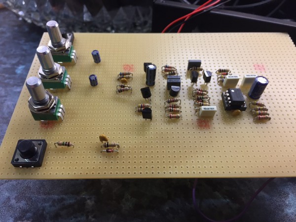
Hey All,
The last couple of weeks I've tried to get this strip board up and running but I'm afraid I'm stuck.. I was wondering if somebody who has finished this board successfully can give me some voltage values at some points on the board so I can track down the problem.
First, my setup:
- I've build a +/- 12V power supply and connected it to the stripboard with an extra +12V going into the accent
- the trigger is connected to a Highly Liquid MD24 board output (which gives +5V pulses, i've checked that)
- I've plugged in the output into my mixer
I've measured the voltages on the TL072, and they read + and -12 on pin 4 & 8, so that is getting power. However, I don't see anything coming out of T3. There is +12V on the collector but the base isn't getting anything from the trigger (I think..  ) )
Anyway, I was wondering, in this thread I've read something about supplying voltages to some points to manually trigger this circuit, but what points should that be?
Thanks in advance!
| Description: |
|
| Filesize: |
2.05 MB |
| Viewed: |
960 Time(s) |
| This image has been reduced to fit the page. Click on it to enlarge. |

|
|
|
|
Back to top
|
|
|
RotomotioN

Joined: Mar 02, 2013
Posts: 9
Location: Netherlands
|
| Posted: Wed Mar 06, 2013 7:12 pm Post subject:
|
|
|
Hey Gerbster
You need a momentary switch between +V and the normal trigger input point |
|
|
Back to top
|
|
|
elmegil

Joined: Mar 20, 2012
Posts: 2179
Location: Chicago
Audio files: 16
|
| Posted: Wed Mar 06, 2013 7:36 pm Post subject:
|
|
|
I don't know that I'd agree on a momentary...
There has to be positive voltage on both of the inputs for there to be a trigger. How much positive voltage can have a significant impact on how loud / hard a hit you get out of it.
Some people hook the accent (the "northern" input) to +V all the time. Others hook the two inputs together. In the original there wasn't any trigger conditioning (the diode and cap arrangement on the input) and you had the "common clock" (a combination of the clock and variable accent on steps when it was active, ranging from 4 to 14V) gated by the instrument step (5V).
I've found though, attempting to do it "the right way", something must be different about the modern components, because even with no instrument gate, I will get a trigger from a sufficiently high accent + clock. What I've done is tie those two together, and I'm generating the 1ms pulse from an Arduino so I don't have to worry about conditioning the input. If I were to make this a module, I'd use the conditioner though (I've got it on the stripboard, I just bypass it with the gate input). |
|
|
Back to top
|
|
|
elmegil
Joined: Mar 20, 2012
Posts: 2179
Location: Chicago
Audio files: 16
|
|
|
Back to top
|
|
|
gerbster
Joined: Nov 13, 2012
Posts: 2
Location: Breda, The Netherlands
|
| Posted: Thu Mar 07, 2013 6:44 am Post subject:
I'm an idiot |
|
|
Well, it turned out i'm an idiot. After building a complete new 808 BD pcb from scratch that DID work i found that... I connected the output wire to the wrong pin of my output socket.
so now i have 2 fully working 808 BD's  But thanks for your replies. But thanks for your replies. |
|
|
Back to top
|
|
|
Snaper
Joined: Feb 28, 2014
Posts: 217
Location: Hungary
|
| Posted: Fri Jun 27, 2014 10:00 pm Post subject:
|
|
|
Oouch, got every parts "in stock", except the two 0.47u caps.
Can I use 1u? |
|
|
Back to top
|
|
|
elmegil
Joined: Mar 20, 2012
Posts: 2179
Location: Chicago
Audio files: 16
|
| Posted: Sat Jun 28, 2014 6:45 am Post subject:
|
|
|
They make up filters on the output section so doubling the size of the two caps will change the sound.
However, two 1uF caps in series will make .5uF capacitance which would be quite close.
Not sure how you'd fit that onto the stripboard, but there's probably a way. |
|
|
Back to top
|
|
|
Snaper
Joined: Feb 28, 2014
Posts: 217
Location: Hungary
|
| Posted: Sat Jun 28, 2014 7:04 am Post subject:
|
|
|
| elmegil wrote: | They make up filters on the output section so doubling the size of the two caps will change the sound.
However, two 1uF caps in series will make .5uF capacitance which would be quite close.
Not sure how you'd fit that onto the stripboard, but there's probably a way. |
I see. Already ordered a couple from Tayda, just have some freetime, and anything else is here in stock 
Then waiting... |
|
|
Back to top
|
|
|
Snaper
Joined: Feb 28, 2014
Posts: 217
Location: Hungary
|
| Posted: Sat Jul 19, 2014 1:26 pm Post subject:
|
|
|
| -minus- wrote: | | LektroiD wrote: | | -minus- wrote: | | Changing the DECAY pot to a 1M seems to hold the decay forever when fully dialed. |
This seems to make the decay appear to feed back, and starts pitching upwards by a semitone when fully dialled on mine. I think it is possible to reduce the resistance by putting another resistor either in series of parallel (I can't remember which way around it is), but I should be able to level it out with a trimmer.. Or, I could just leave it as a 'feature'.
| Quote: | | I've probed around the circuit a bit with a piece of wire without any detrimental results... I hope! I put another pot (500K) between the left leg of R18 and the right leg of R23 and by turning it, it makes the kick drum sound like toms. |
from which angle are you taking 'left & right'? Also are you referring to the schematic, the stripboard (which is laid out vertically) or the perfboard layout? I tried all combinations of this with a 470K resistor, but nothing happened.. Can you please indicate what else is in the junction of 'left' and 'right' legs?
I don't think I'll build another one just yet, I'll wait until the triggering problems have been ironed out of this, which will hopefully get rid of the audible 'trigger' click.. |
My 1M pot seems to go a bit wild too... I guess fully dialed was a bit of an overstatement. There's a point where it extends the decay a lot though.
Ok... the mysterious tom pot. I've just switched on this breadboard version... Looking at the perf board layout, it's from the link between pin 5 of the IC (TL072) and the 22K resistor (R18).... and the link between the 470K resistor (R23) and C6. This is where I'm putting the 500K B pot. (the neck bone is connected to the back bone...etc)
I'm triggering manually with one of the methods described earlier. Not that this would matter I guess.
To be honest, I really don't know what I'm doing! You are probably much more experienced in these matters than myself...
Anyway, hopefully someone else can work out a click-less triggering method! I'm really unsure what Krunkus meant by: The notes say that Accent needs to be held high by at least 2V or the trigger won't work. I'd try holding it at 6V and then try triggering as normal.
I mean, as one can clearly see, I don't even know how to post quotes on a forum correctly, let alone work out what anyone is talking about here most of the time! Don't even know what day it is....
 |
I would like to do this "Tom mod"...but...its not clear.
Could please be a bit specific?
Im ok with the board part, but what about the 500k pot connections? |
|
|
Back to top
|
|
|
Snaper
Joined: Feb 28, 2014
Posts: 217
Location: Hungary
|
| Posted: Sun Jul 20, 2014 5:44 am Post subject:
|
|
|
So, I've finished mine...but...
Well it's always "sounds"...
I mean ican trigger, and hear the click etc, but it seems that there is no decay:S |
|
|
Back to top
|
|
|
Snaper
Joined: Feb 28, 2014
Posts: 217
Location: Hungary
|
| Posted: Sun Jul 20, 2014 10:13 am Post subject:
|
|
|
Ignore my last post!
Decay and pitch mod pots was not working
Replaced them and now : BoOooOoOm
Note for future builders : pot lugs are numbered from back of the pot in the original stripboard layout, but the pitch mod pot numbered from the front!
Ive used 1M for decay, no pitch problem even if its fully open, and 100k for the pitch mod.
Finished board working in my eurorack fine!
Used the accent pot drawing, with a 100k pot.
Module triggered now from a square wave lfo:)
Thanks for the layout!
Now have to mobe to the snare |
|
|
Back to top
|
|
|
Karlisss
Joined: Apr 20, 2015
Posts: 25
Location: Latvia (EU)
|
| Posted: Sat Aug 01, 2015 3:27 am Post subject:
|
|
|
| so, in the first stripboard image in post, now is correct version? |
|
|
Back to top
|
|
|
Alfredo
Joined: Nov 20, 2008
Posts: 52
Location: Spain
|
| Posted: Thu Aug 06, 2015 1:10 pm Post subject:
rimshot 808 |
|
|
Please mates, anyone 808´s stripboard/veroboard ??
Thanks. |
|
|
Back to top
|
|
|
lysergist
Joined: Jan 14, 2016
Posts: 36
Location: France
Audio files: 2
|
| Posted: Tue Jul 05, 2016 6:42 pm Post subject:
|
|
|
I tried some mods out of this topic but i best i've found for the pitch is that one, coming from the e-licktronic forum in this thread : http://www.e-licktronic.com/forum/viewtopic.php?f=18&t=143
BassDrum Tuning -- replaced R165 (47k) with SPDT switch that selects between original value (47k) and a 100k potentiometer (audio/log preferably)
and
BassDrum Tuning Envelope -- replaced R166 (6.8k) with SPDT switch that selects between original value (6.8k) and a 5k potentiometer in series with a 2k resistor. (in combination with the tuning mod, this mod enables some nice extra-punchy bass drums!)
In this layout those resistors are R13 and R14.
Last edited by lysergist on Mon Feb 17, 2020 9:18 am; edited 2 times in total |
|
|
Back to top
|
|
|
Late_to_the_party
Joined: Sep 24, 2017
Posts: 21
Location: London
|
| Posted: Wed Oct 18, 2017 11:11 am Post subject:
|
|
|
Hello all.
My first post too.
I just wanted to say, what a brilliant thread. Well done for all the hard work put in by everyone. Thank you LektroiD. Thank you to -minus- for the layouts. elmegil thanks for the helpful tips and comments too.
You have given me the confidence to try my first project ever. I'm have begun with the Kick module only, and move on to the other modules later. I have attempted the Kick module on perfboard as per Eric Archer's layout.
http://www.ericarcher.net/wp-content/uploads/2014/07/tr-808-bass-drum-diy-project.pdf
I make music by sequencing in Logic and at the moment I am content with making a few boxes, that spit out a drum noise at the push of a button, then I can sample them and work into a track.
Therefore I have added a momentary push switch to ‘trigger’.
I have read through this post and the specific kick drum thread. But I have completed my wiring and have no sound. I’ve double checked all components and wiring and all seems correct.
Now for my (probably very stupid) questions:
1. Is the problem my momentary push switch not creating the correct kind of trigger?
2. Should I be connecting ‘out’ and ‘gnd’ to the output jack? Does polarity matter?
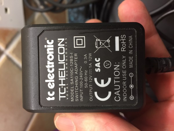
3. Sadly out of stupidity I wired this circuit up with AC 14V. I now have wired it up with 12V DC. But I’m so confused. A friend who knows more than me said, a simple 12V DC won’t work it has to be Dual +/- DC. I now am so confused as to power supply. Please advise.
Thanks for any help in advance.
JM
| Description: |
|
| Filesize: |
617.03 KB |
| Viewed: |
591 Time(s) |
| This image has been reduced to fit the page. Click on it to enlarge. |
|
| Description: |
|
| Filesize: |
529.54 KB |
| Viewed: |
579 Time(s) |
| This image has been reduced to fit the page. Click on it to enlarge. |
|
|
|
|
Back to top
|
|
|
lysergist
Joined: Jan 14, 2016
Posts: 36
Location: France
Audio files: 2
|
| Posted: Wed Oct 18, 2017 12:24 pm Post subject:
|
|
|
You definitly need a transformer + dual power supply, you can't achieve that with the one you have. You need a transformer that outputs 2*15v AC or 12v. Then a simple power supply converts it to symetric +15V/-15V DC
Google "dual power supply" you'll find a lot of schems.
To test the triggering tie the accent to +V, then you could trig with any kind of voltage from around 3V to 15V. |
|
|
Back to top
|
|
|
Late_to_the_party
Joined: Sep 24, 2017
Posts: 21
Location: London
|
| Posted: Wed Oct 18, 2017 1:09 pm Post subject:
|
|
|
Thank you lysergist. Thanks for the speedy reply, I had been scratching my head on this for ages. I have a undergraduates physics degree but had never heard of a dual power supply.
So the best option is to DIY the power supply too? |
|
|
Back to top
|
|
|
PHOBoS
Joined: Jan 14, 2010
Posts: 5792
Location: Moon Base
Audio files: 709
|
| Posted: Thu Oct 19, 2017 2:32 am Post subject:
|
|
|
An easy way to make a dual supply would be to use an AC wallwart (not DC) of 15...18V. Some excellent information on
how to use it to create a dual supply can be found on the MFOS site here. (use LM7815/LM7915 instead of LM7812/LM7912).
I am assuming that 2x 9V is too low for this circuit or you could use 2 batteries. hmm, 2 12V DC wallwarts could work too actually.
_________________
"My perf, it's full of holes!"
http://phobos.000space.com/
SoundCloud BandCamp MixCloud Stickney Synthyards Captain Collider Twitch YouTube |
|
|
Back to top
|
|
|
Late_to_the_party
Joined: Sep 24, 2017
Posts: 21
Location: London
|
|
|
Back to top
|
|
|
Late_to_the_party
Joined: Sep 24, 2017
Posts: 21
Location: London
|
| Posted: Wed Oct 25, 2017 3:15 am Post subject:
|
|
|
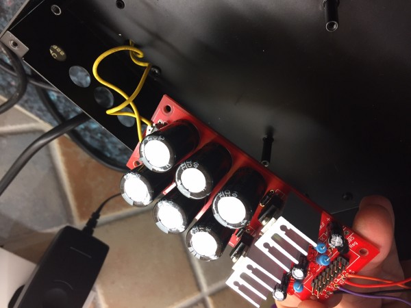
Got my DIY power supply last night... made it, hooked it up to my 808 BD, all excited, and...
NOTHING
I had to change all the transistors as I possibly damaged them when I hooked it up to an AC supply like an idiot, before it was pointed out to me what a bipolar supply was.
BOOOOOOOOOM! it worked.
However, I noticed in my replacing the transistors a ground jumper had come loose. When I Resoldered it... Nothing again.
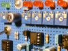
Disconnect it and it works again. The Ground is connecting C1, R20, R25 in the schematic below. Are they necessary? It works without them.
I will say it does seem a little noisy... Is it affecting the gain some how? So I have a high signal to noise ratio?
On a different note; is there a good mod to get more drive/distorsion?
Something like a pot between +15 and the op amp?
| Description: |
|
| Filesize: |
706.9 KB |
| Viewed: |
548 Time(s) |
| This image has been reduced to fit the page. Click on it to enlarge. |

|
| Description: |
|
| Filesize: |
475.5 KB |
| Viewed: |
565 Time(s) |
| This image has been reduced to fit the page. Click on it to enlarge. |
|
| Description: |
|
| Filesize: |
462.89 KB |
| Viewed: |
604 Time(s) |
| This image has been reduced to fit the page. Click on it to enlarge. |

|
|
|
|
Back to top
|
|
|
PHOBoS
Joined: Jan 14, 2010
Posts: 5792
Location: Moon Base
Audio files: 709
|
| Posted: Wed Oct 25, 2017 6:30 am Post subject:
|
|
|
| Apollo View wrote: | | Disconnect it and it works again. The Ground is connecting C1, R20, R25 in the schematic below. Are they necessary? It works without them. |
I think C1 is used as a filter capacitor to filter out any high frequency noise, so the circuit works without it but might
produce a bit more noise and maybe it also prevents some unwanted oscilllations.
R20 biases the base of the transistor to GND. If the circuit isn't producing sound and R20 isn't attached then the base
of the transistor is basically floating because of C9. In practise a capacitor does not have an infinite resistance and the
base of the transistor isn't completely isolated from the emitter so it isn't really floating (which would also amplify noise).
I think if you look at the signal on a scope you will clearly see a difference in the output signal with or without R20 though.
R25 biases the output to GND but this is also done by anything you connect it too unlesss it has a really high impedance.
It should elimate any pops when plugging something into the output but for the rest the circuit should work just as well.
_________________
"My perf, it's full of holes!"
http://phobos.000space.com/
SoundCloud BandCamp MixCloud Stickney Synthyards Captain Collider Twitch YouTube |
|
|
Back to top
|
|
|
|

 Forum index » DIY Hardware and Software » The layout factory
