| Author |
Message |
Mirmite
Joined: Mar 21, 2012
Posts: 9
Location: sweden
|
|
|
Back to top
|
|
 |
Snaper
Joined: Feb 28, 2014
Posts: 217
Location: Hungary
|
 Posted: Sat Mar 08, 2014 3:00 pm Post subject: Posted: Sat Mar 08, 2014 3:00 pm Post subject:
|
  |
|
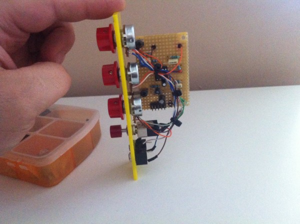
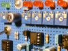
Updated layout attached, tested and working!!!
| Description: |
|
| Filesize: |
91.36 KB |
| Viewed: |
989 Time(s) |
| This image has been reduced to fit the page. Click on it to enlarge. |

|
| Description: |
|
| Filesize: |
2.18 MB |
| Viewed: |
871 Time(s) |
| This image has been reduced to fit the page. Click on it to enlarge. |
|
|
|
|
Back to top
|
|
|
bamboombaps
Joined: Oct 23, 2015
Posts: 66
Location: Glasgow
|
| Posted: Wed Dec 30, 2015 8:07 am Post subject:
|
|
|
hey thanks for this! im building this now- can you help?
i dont quite understand how to wire the pots and sockets and what is the switch? |
|
|
Back to top
|
|
|
Snaper
Joined: Feb 28, 2014
Posts: 217
Location: Hungary
|
| Posted: Wed Dec 30, 2015 8:53 am Post subject:
|
|
|
Hi, Sure, I will try.
Input and output pots are just attenuators, so leg 1 into ground, leg 3 is the input, leg 2 is the out.
About the dist pot and the switch, here is the original schematic :
http://legacy.hexinverter.net//files/projects/batteryacid-v10/batteryACID_v1.0_schematic.png
Leg 1 of the dist pot is not connected leg 2 is to the pad (on the layout), and leg 3 to ground.
As you can see, the switch is a simple spdt switch.
Do not forget, that the white little dots means that those jumpers are joined there, so you have to use two little jumpers  |
|
|
Back to top
|
|
|
bamboombaps
Joined: Oct 23, 2015
Posts: 66
Location: Glasgow
|
| Posted: Wed Jan 06, 2016 8:04 pm Post subject:
|
|
|
hey thanks alot for this, im waiting on the IC and pots but looking forward to getting it up and running.
btw all the pots are Log, is that correct? if not i have lin ones in my bits box |
|
|
Back to top
|
|
|
Snaper
Joined: Feb 28, 2014
Posts: 217
Location: Hungary
|
| Posted: Wed Jan 06, 2016 9:18 pm Post subject:
|
|
|
| IIRC I used linear pots for all three what I built;) |
|
|
Back to top
|
|
|
bamboombaps
Joined: Oct 23, 2015
Posts: 66
Location: Glasgow
|
| Posted: Mon Apr 18, 2016 9:16 am Post subject:
|
|
|
so i built this and theres something wrong.
when i turn the distortion pot up and down it just turns the voume up and down, there is no distortion to be heard at all.
the signal is travelling stright through without effect. when the switch is switched it only allows the distortion pot to adjust volume.
ive re-flowed the whole board but nothing
any ideas? |
|
|
Back to top
|
|
|
blue hell
Site Admin

Joined: Apr 03, 2004
Posts: 24390
Location: The Netherlands, Enschede
Audio files: 296
G2 patch files: 320
|
| Posted: Mon Apr 18, 2016 12:24 pm Post subject:
|
|
|
| bamboombaps wrote: | | any ideas? |
Sounds like the levels over the diodes are not high enough to get them conducting (and then distorting the signal). Some causes could be :
- too low an input level.
- not enough amplification in the opamp stage, likely caused by a wrongly valued resistor.
- too much load on the output, like for instance connecting headphones to it directly.
_________________
Jan
also .. could someone please turn down the thermostat a bit.
 |
|
|
Back to top
|
|
|
Grumble
Joined: Nov 23, 2015
Posts: 1310
Location: Netherlands
Audio files: 30
|
| Posted: Mon Apr 18, 2016 11:53 pm Post subject:
|
|
|
Any soundbites as how this module is supposed to sound?  |
|
|
Back to top
|
|
|
Grumble
Joined: Nov 23, 2015
Posts: 1310
Location: Netherlands
Audio files: 30
|
| Posted: Tue Apr 19, 2016 4:37 am Post subject:
|
|
|
| Snaper wrote: | | Leg 1 of the dist pot is not connected leg 2 is to the pad (on the layout), and leg 3 to ground |
Just a small remark on this: it is common practice to attach the non used pin of a potmeter to the runner (center pin) of the potmeter, in that case, in the event of a bad spot on the substrate, the resistance will not be infinitive but the max value of the pot. |
|
|
Back to top
|
|
|
PHOBoS
Joined: Jan 14, 2010
Posts: 5792
Location: Moon Base
Audio files: 709
|
| Posted: Wed Apr 20, 2016 1:10 pm Post subject:
|
|
|
what are you using as your sound source ?
as Blue Hell mentioned if the level is too low it won't clip, but with the amplification being adjustable to >200x
and the voltage drop over the diodes being 1V that would be a very low signal level (< 0,005V). Another thing, if you are using
a square wave you might not hear the effect. Do you have a scope so you can see what the output level is ? an AC Volt meter
might work too with a simple sinewave on the input but a scope would be much more useful.
You say the distortion pot works as a level control so you seem to have something correct, because it simply adjusts the gain and
that would sound like that if the signal wasn't being clipped. Using the schematic posted here there are a couple things you could check:
1M resistor R4 (if it is too small it would attenuate the input signal)
10K resistor R5 (if it is too big the signal would also be attenuated)
1M resistor R1 (if it too small you won't get enough gain)
diodes D1, D2 (if not connected correctly the signal won't get clipped)
Also since it is stripboard there is a higher change of shorts between traces, but since you are getting a signal out I doubt that is the case.
And last but not least, as Snaper mentioned:
Do not forget, that the white little dots means that those jumpers are joined there, so you have to use two little jumpers.
If you didn't do that the circuit probably wouldn't have worked at all though, but I noticed that one of those connects the diodes to GND.
on a side note, the 1M resistor R8 seems useless to me. It is parallel to the 100K pot and too large to make much of a difference. 
_________________
"My perf, it's full of holes!"
http://phobos.000space.com/
SoundCloud BandCamp MixCloud Stickney Synthyards Captain Collider Twitch YouTube |
|
|
Back to top
|
|
|
bamboombaps
Joined: Oct 23, 2015
Posts: 66
Location: Glasgow
|
| Posted: Mon Apr 25, 2016 6:32 am Post subject:
|
|
|
| PHOBoS wrote: | what are you using as your sound source ?
as Blue Hell mentioned if the level is too low it won't clip, but with the amplification being adjustable to >200x
and the voltage drop over the diodes being 1V that would be a very low signal level (< 0,005V). Another thing, if you are using
a square wave you might not hear the effect. Do you have a scope so you can see what the output level is ? an AC Volt meter
might work too with a simple sinewave on the input but a scope would be much more useful.
You say the distortion pot works as a level control so you seem to have something correct, because it simply adjusts the gain and
that would sound like that if the signal wasn't being clipped. Using the schematic posted here there are a couple things you could check:
1M resistor R4 (if it is too small it would attenuate the input signal)
10K resistor R5 (if it is too big the signal would also be attenuated)
1M resistor R1 (if it too small you won't get enough gain)
diodes D1, D2 (if not connected correctly the signal won't get clipped)
Also since it is stripboard there is a higher change of shorts between traces, but since you are getting a signal out I doubt that is the case.
And last but not least, as Snaper mentioned:
Do not forget, that the white little dots means that those jumpers are joined there, so you have to use two little jumpers.
If you didn't do that the circuit probably wouldn't have worked at all though, but I noticed that one of those connects the diodes to GND.: |
Foniks 555 TH VCO is my source, tried with a scope and although the sine shape is being affected (slightly) but there is no audible change.
I'm pretty sure all connections are correct, all values have been triple checked and reflowed numerous times. im starting to suspect the IC, or even the stipboard itself.
ill rebuild on better quality stip and see what happens.
not letting this one go! |
|
|
Back to top
|
|
|
Snaper
Joined: Feb 28, 2014
Posts: 217
Location: Hungary
|
| Posted: Mon Apr 25, 2016 6:43 am Post subject:
|
|
|
| Phobos got the point there. I think checj the jumpers. The little dots means that there are actually two jumpers are connected together. (2 wires in 1 hole) |
|
|
Back to top
|
|
|
bamboombaps
Joined: Oct 23, 2015
Posts: 66
Location: Glasgow
|
| Posted: Mon Apr 25, 2016 8:13 am Post subject:
|
|
|
| Snaper wrote: | | Phobos got the point there. I think checj the jumpers. The little dots means that there are actually two jumpers are connected together. (2 wires in 1 hole) |
yeah man i caught the double jumpers. everything seems right
its small enough to do again from scratch |
|
|
Back to top
|
|
|
PHOBoS
Joined: Jan 14, 2010
Posts: 5792
Location: Moon Base
Audio files: 709
|
|
|
Back to top
|
|
|
bamboombaps
Joined: Oct 23, 2015
Posts: 66
Location: Glasgow
|
| Posted: Mon Apr 25, 2016 2:11 pm Post subject:
|
|
|
Here are a couple of pics. First one straight from the sine output of the 555 vco
Second one is with all pots cw. Input and output pots adjust level as expected. Distortion switch and pot do nothing , sorry this is different from what I thought I had observed in that the dist pot doesn't work at all. Even when bridged at the lugs with a wire to test.
| Description: |
|
| Filesize: |
2.78 MB |
| Viewed: |
409 Time(s) |
| This image has been reduced to fit the page. Click on it to enlarge. |

|
| Description: |
|
| Filesize: |
2.74 MB |
| Viewed: |
370 Time(s) |
| This image has been reduced to fit the page. Click on it to enlarge. |

|
|
|
|
Back to top
|
|
|
PHOBoS
Joined: Jan 14, 2010
Posts: 5792
Location: Moon Base
Audio files: 709
|
|
|
Back to top
|
|
|
lilpaula87
Joined: May 11, 2020
Posts: 12
Location: Italy
|
| Posted: Fri Dec 11, 2020 7:21 am Post subject:
|
|
|
Hi there, I’ve just finished this module but I’m not sure about its behavior.
In details, I’ve noticed:
1. The output level is lower then the input level
2. Passing through the module the sound loses part of the low frequencies
3. Turning up the distortion pot the effect amount grows as expected but when the pot reaches 9 out of 10 of the dial scale, suddenly the distortion boosts hudgely.
If you have built this module, could you please tell me if this is its normal behavior? |
|
|
Back to top
|
|
|
|

 Forum index » DIY Hardware and Software » The layout factory


