| Author |
Message |
deltamodulator
Joined: May 18, 2016
Posts: 91
Location: Texas, USA
Audio files: 2
|
|
|
Back to top
|
|
 |
Vo1t

Joined: Feb 25, 2011
Posts: 6
Location: L. A.
Audio files: 2
|
 Posted: Mon Jun 27, 2016 10:13 am Post subject: Posted: Mon Jun 27, 2016 10:13 am Post subject:
|
  |
|
A spiral would allow you to change pitch smoothly by spinning your finger, then quantized jumps by swiping across spiral zones. Smooth or Jumps in one easy controller, this is genius!
_________________
Vo1t |
|
|
Back to top
|
|
|
deltamodulator
Joined: May 18, 2016
Posts: 91
Location: Texas, USA
Audio files: 2
|
| Posted: Mon Jun 27, 2016 11:05 am Post subject:
|
|
|
| Vo1t wrote: | | A spiral would allow you to change pitch smoothly by spinning your finger, then quantized jumps by swiping across spiral zones. Smooth or Jumps in one easy controller, this is genius! |
Yes, that seems worth doing. I know how to make a spiral that responds like that, but the question is.. how do we make a resistor or potentiometer that works that way? I'm thinking of a flat underlying circle and the spiral on top... just not sure what will work.
Les |
|
|
Back to top
|
|
|
blue hell
Site Admin

Joined: Apr 03, 2004
Posts: 24673
Location: The Netherlands, Enschede
Audio files: 330
G2 patch files: 320
|
| Posted: Mon Jun 27, 2016 3:04 pm Post subject:
|
|
|
I like that spiral idea .. but apart from the practical issue of how to turn it into a voltage source ... I'm trying to work out some math on it .. the resistance per unit length would have to vary with the spiral's length, or the angle (defining a spirial in polar coordinates as r = a.Phi).
Say .. you want a move of one step (corresponding to a 2.Pi 'rotation') to amount to a semitone, or maybe to a 3rd .. or maybe 3 semitones would be a nice step value ... Now depending on if you want linear or exponential control from it the resistance will have to vary in some way.
Let's assume linear then for every 2 Pi the resistance change would need be the same, but the path length increases with angle, so the track will have to get wider to get the same resistance per unit length.
In the end you will want expo control ... probably ... like a 1 Volt change will give a frequency change of 1 octave for a controlled oscillator .. so maybe the resistance change could be matched to that .. but I didn't dare to think of the math involved in that yet. EDIT: But an expo converter could be used as well of course to go from linear to expo.
Anyway ... not only is it an interesting controller idea, it's an interesting math puzzle too :-)
Edit2 : I was assuming a higher pitch on going out on the spiral more, but could invert that too, in the case of expo control that would prolly result in a narrower trace going outward ... which may be more practical for playing it?
_________________
Jan
also .. could someone please turn down the thermostat a bit.

9 3 4 .. erm .. not 13 then? .. hmm, ah eight! .. yeah yeah as in 8647 .. 47 is an 88 .. pwew .. numbles!
Last edited by blue hell on Mon Jun 27, 2016 3:36 pm; edited 4 times in total |
|
|
Back to top
|
|
|
blue hell
Site Admin
Joined: Apr 03, 2004
Posts: 24673
Location: The Netherlands, Enschede
Audio files: 330
G2 patch files: 320
|
| Posted: Mon Jun 27, 2016 3:14 pm Post subject:
|
|
|
Oh, and for constructional ideas, maybe the approach people use for ribbon controllers could work. Basically that is a resistive element separated from a good conductor by some spacer, such that when you press at some point the resistor gets connected to the conductor there. There should be plenty of practical info about ribbon controllers on the webs, and at least three ideas on this forum as well.
_________________
Jan
also .. could someone please turn down the thermostat a bit.
9 3 4 .. erm .. not 13 then? .. hmm, ah eight! .. yeah yeah as in 8647 .. 47 is an 88 .. pwew .. numbles! |
|
|
Back to top
|
|
|
deltamodulator
Joined: May 18, 2016
Posts: 91
Location: Texas, USA
Audio files: 2
|
| Posted: Mon Jun 27, 2016 5:08 pm Post subject:
|
|
|
Funny you should mention the idea of putting another resistive layer underneath the spiral, as I was reflecting on just such a notion. Thanks for taking it a step further and informing me that this is how ribbon controllers work.
The variation of voltage change with radius could be adjusted by varying the thickness of the spiral in the z direction. With 3D printing we of course control the vertical, at least to some degree. Also this opens up the possibility of all manner of crazy structures, spirals wrapped around spheres, cones, a flute controller that looks like a flute, or whatever.
I'd be interested in what might conjure up in your bright mind in the 3D printing space - I've always held you in high regard mentally as you know Jan.
Les |
|
|
Back to top
|
|
|
deltamodulator
Joined: May 18, 2016
Posts: 91
Location: Texas, USA
Audio files: 2
|
| Posted: Mon Jun 27, 2016 9:02 pm Post subject:
|
|
|
Excitement! I thought and thought of a way to do this. You see, it's not very simple because well, of a hundred problems. It became clear to me, as if divine inspiration guided my thoughts (which we know is true), as I created the CAD file.
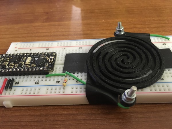
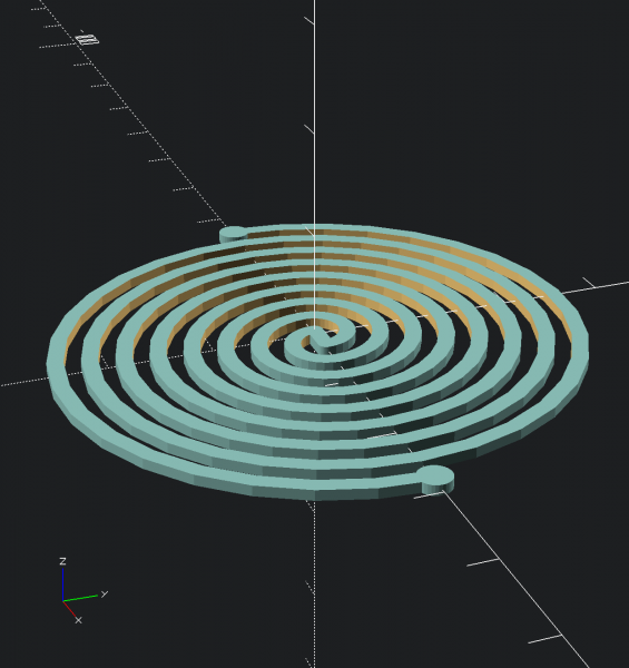
It turns out that by interlocking two spirals I was able to make a varistor! This will be my first product. Vo1t, would you like to be the first customer? The model shown is defined by the following parameters:
| Code: | num = 4; // number of loops in controller
radius = 25; // radius of controller
thickness = 1; // thickness of traces
$fn = 32; // number of facets on round parts
|
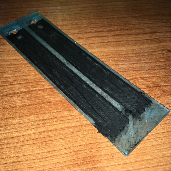
It is very fragile in this form, however with care it has not broken yet. I measure it to be 68 kOhm untouched. Then as I move it around, it gets as low as 10 or 20 kOhm or lower (I didn't notice the bottom end too much).
Actually the test setup kinda sucks right now because I'm using both hands to hold the probes and an extra finger to move it around. I need to make some way of attaching the leads on either end. Also it probably should have a base of some type with mounting holes.
Tell me what you think?
Les
| Description: |
| photo of first prototype - works great! |
|
| Filesize: |
1.84 MB |
| Viewed: |
574 Time(s) |
| This image has been reduced to fit the page. Click on it to enlarge. |

|
| Description: |
| CAD image of Finger Pot 2 design |
|
| Filesize: |
43.3 KB |
| Viewed: |
533 Time(s) |
| This image has been reduced to fit the page. Click on it to enlarge. |
|
|
|
|
Back to top
|
|
|
deltamodulator
Joined: May 18, 2016
Posts: 91
Location: Texas, USA
Audio files: 2
|
|
|
Back to top
|
|
|
RingMad

Joined: Jan 15, 2011
Posts: 430
Location: Montreal, Canada
Audio files: 4
|
| Posted: Tue Jun 28, 2016 4:32 am Post subject:
|
|
|
Cool stuff!
.:James:. |
|
|
Back to top
|
|
|
Grumble

Joined: Nov 23, 2015
Posts: 1320
Location: Netherlands
Audio files: 30
|
| Posted: Tue Jun 28, 2016 1:38 pm Post subject:
|
|
|
| I'm sure that by useing an Arduino with an apropiate conversion program it is very possible to get the right voltages. |
|
|
Back to top
|
|
|
deltamodulator
Joined: May 18, 2016
Posts: 91
Location: Texas, USA
Audio files: 2
|
| Posted: Tue Jun 28, 2016 1:57 pm Post subject:
|
|
|
| Grumble wrote: | | I'm sure that by useing an Arduino with an apropiate conversion program it is very possible to get the right voltages. |
Funny you should mentiont that, Grumble! That is exactly what I put together this morning. I am just putting the unmapped numbers into an oscillator's frequency right now, so the "apropriate conversion program" is not quite in place, I guess that's the next job to do.
I had it working with OSC over to ChucK but for some reason now that is broken. Processing can be touchy about communications it seems...
The controller has some nonlinear behavoiurs that are OK i guess, just have to figure them out. One promising thing is it may (or maybe isn't) detecting my pulse. More on that to follow.
I'll print some more of these soon so I can share them with others.
Les |
|
|
Back to top
|
|
|
deltamodulator
Joined: May 18, 2016
Posts: 91
Location: Texas, USA
Audio files: 2
|
| Posted: Tue Jun 28, 2016 2:39 pm Post subject:
|
|
|
I have been just playing around with the sensor for a while now and I'm concluding that a better way of making electrical contact is necessary. It keeps behaving somewhat erratically.
So later tonight when I get back into this I'll use some m3 hardware that I have in a Harbor Freight kit and use that to establish really good electrical AND mechanical connections. Then the results will be more readily evaluated.
Also I think it is picking up the 60 Hz from the body in air, so I will make a ground contact to minimize that.
Les |
|
|
Back to top
|
|
|
deltamodulator
Joined: May 18, 2016
Posts: 91
Location: Texas, USA
Audio files: 2
|
| Posted: Wed Jun 29, 2016 8:04 am Post subject:
|
|
|
I secured the electrical but not mechanical connections and the device became somewhat more expressive. Next I will make a couple of wiring mods and get some mechanical stability to improve the sensitivity.
I am a bit disappointed of this device as a controller per se, as it is less expressive than I had imagined in my mind. It is, however sufficiently expressive to be fun as a wonky control of sound, very exploratory and interactive. Fun for play.
I am thinking of designing multiple port versions and adding a mechanical base for the things.
Also I have one for sale. I'd like to see $5 for it if anyone wants to buy it. Basically it replaces one potentiometer in a test circuit or even in a small enclosed system. I'll also put the files up on Thingiverse for anyone who wants to print their own.
I can't promise any other items for sale yet because printing these things is a bit hit or miss and I can't guarantee to have anything in stock at any given time...
Les |
|
|
Back to top
|
|
|
deltamodulator
Joined: May 18, 2016
Posts: 91
Location: Texas, USA
Audio files: 2
|
| Posted: Wed Jun 29, 2016 12:29 pm Post subject:
|
|
|
OOPS I forgot that I cannot ever sell anything for any amount. Sorry bout that.
Les |
|
|
Back to top
|
|
|
deltamodulator
Joined: May 18, 2016
Posts: 91
Location: Texas, USA
Audio files: 2
|
| Posted: Thu Jun 30, 2016 5:52 pm Post subject:
|
|
|
Never mind anyway, I do not seem to be able to reliably create these things.
Sigh.
Les |
|
|
Back to top
|
|
|
deltamodulator
Joined: May 18, 2016
Posts: 91
Location: Texas, USA
Audio files: 2
|
|
|
Back to top
|
|
|
Grumble
Joined: Nov 23, 2015
Posts: 1320
Location: Netherlands
Audio files: 30
|
| Posted: Sun Jul 03, 2016 9:26 pm Post subject:
|
|
|
Just thinking: isn't it possible to fill up the space between the windings of the spiral with a printed isolator?
So than you get a more mechanical stable device. |
|
|
Back to top
|
|
|
deltamodulator
Joined: May 18, 2016
Posts: 91
Location: Texas, USA
Audio files: 2
|
| Posted: Sun Jul 03, 2016 10:25 pm Post subject:
|
|
|
| Grumble wrote: | Just thinking: isn't it possible to fill up the space between the windings of the spiral with a printed isolator?
So than you get a more mechanical stable device. |
Hi Grumble, thanks for your help and interest so far, I appreciate the ideas. Filling the space between the spirals with an insulator is an interesting concept.
First the argument against it is then you'd get a fused device with no variation. So you must not intend to say that the space is mechanically bonded with the insulation, at least not on both sides. Perhaps you are saying to have it attached on one side and not the other, or just in-between free floating. That must be your intention.
In those two cases, the insulation would prevent shorts between the spirals, which is kind of like the shall we say "macroscopic" behavior, and also prevent the sliding of one loop against another, which shall we say is the "adjacent" audio effect. The only thing left would be very subtle changes in resistance due to deformation of the shape.
I would have to say that your suggestion makes it a different beast, less coarse, less crude, and more gentle and elegant. I like it. The total variation in resistance would be much lower and it might become coarser by using fewer ADC bits, but then we could make interesting circuit structures such as a fully printed bridge format.
Straying off-of-your-topic a bit, I have had the idea of adding more spirals from the central point. The programming of the spirals must be changed for this, and I do know how to do the work. Once properly modeled, the number of spirals that emerge from the central point can be specified as a parameter, say called "numSpirals", which can be any value from 1 to some arbitrary upper limit determined by other parameters that define the width of the arms and such.
In that case, let us revisit your idea and say that each arm is insulated on one side only, what will happen then? Well it's all conjecture until I try it so let's just leave it at that and try both ideas.
Certainly the number of views on the Thingiverse posting, if valid and not some prank, does indicate that the concept is sparking some great creativity in others and is therefore worth additional exploration. I will give the concept some more thought and also make the change to the spiral algorithm the next time I work on the file.
OK, any other thoughts from Grumble or anyone else are certainly welcome.
Les out, praise the Lord! |
|
|
Back to top
|
|
|
deltamodulator
Joined: May 18, 2016
Posts: 91
Location: Texas, USA
Audio files: 2
|
|
|
Back to top
|
|
|
Grumble
Joined: Nov 23, 2015
Posts: 1320
Location: Netherlands
Audio files: 30
|
| Posted: Sun Jul 03, 2016 11:49 pm Post subject:
|
|
|
Ow.. I think I completely misinterpreted Your meaning of how to use this device...
I thought that by moving a finger over the spiral you would introduce a kind of "shortcut" between the windings of the spiral.
Please enlighten me  how is this contraption ment to work? how is this contraption ment to work? |
|
|
Back to top
|
|
|
deltamodulator
Joined: May 18, 2016
Posts: 91
Location: Texas, USA
Audio files: 2
|
| Posted: Mon Jul 04, 2016 12:24 am Post subject:
|
|
|
Hi Grumble,
I thought the same thing before I built it and hooked it up to an Arduino and wrote the Processing code. The shorting of the finger does nothing because the finger is an insulator compared to the winding's resistance which is in the neighborhood of 10k Ohms to 100k Ohms.
Instead, what I found is that the thing is flexible to the point that you can push the coils together to create shorts, and you can slide the resulting short along the length of the coil by moving laterally. This is the smaller change in Resistance.
To learn to play it well would require understanding and mastery of technique. Also I feel that a larger loop with more coils would be very beneficial.
Les |
|
|
Back to top
|
|
|
Grumble
Joined: Nov 23, 2015
Posts: 1320
Location: Netherlands
Audio files: 30
|
| Posted: Mon Jul 04, 2016 4:15 am Post subject:
|
|
|
| What if you suspend the coil over aluminum foil and ground the foil? |
|
|
Back to top
|
|
|
deltamodulator
Joined: May 18, 2016
Posts: 91
Location: Texas, USA
Audio files: 2
|
| Posted: Mon Jul 04, 2016 4:45 am Post subject:
|
|
|
Then the coil would short out and have zero resistance at all times. Perhaps what you suggest is to place the coil on a surface that was 3D printed in the same material,and that would be interesting to try, yes. I had thought of that before but rejected it as hard to print.. Maybe I should try that next...
Les
Last edited by deltamodulator on Mon Jul 04, 2016 5:46 am; edited 1 time in total |
|
|
Back to top
|
|
|
Grumble
Joined: Nov 23, 2015
Posts: 1320
Location: Netherlands
Audio files: 30
|
| Posted: Mon Jul 04, 2016 4:47 am Post subject:
|
|
|
| Is the coil to weak to be suspended over foil at a height of a few mm's? |
|
|
Back to top
|
|
|
deltamodulator
Joined: May 18, 2016
Posts: 91
Location: Texas, USA
Audio files: 2
|
| Posted: Mon Jul 04, 2016 5:49 am Post subject:
|
|
|
Well, the coil is springy and it flexes downward if you lift it. It can be made thicker and wider to stiffen it up though, but then it would be tough to control. It can also be made thinner and narrower like the first one I made, in which case it has very high resistance and also is not durable enough for an instrument. The happy medium seems to work best.
Les |
|
|
Back to top
|
|
|
|

 Forum index » DIY Hardware and Software » Les Hall's Projects including eChucK