| Author |
Message |
elmegil

Joined: Mar 20, 2012
Posts: 2179
Location: Chicago
Audio files: 16
|
 Posted: Fri Apr 28, 2017 1:50 pm Post subject: Posted: Fri Apr 28, 2017 1:50 pm Post subject:
|
  |
|
| JovianPyx wrote: | | elmegil wrote: | The transistor subs should work, but be aware that the pinouts are opposite (I believe) on the BC* transistors compared to the 2N39* transistors. Double check the data sheets!
As for the 555, if it's not CMOS it won't work right. Not sure the best way to ensure that. |
If you are referring to the nasty habit of the bipolar 555 timer to crowbar the power supply, you can try the PAiA Fatman method (which was sold with bipolar 555 chips). In the Fatman, the crowbar effect caused the VCOs to soft synch when they got close together in pitch. The original design powered the 555 timers through 100 ohm resistors with a 100uF cap across the ICs Vcc and Vee terminals. That works "ok", but PAiA's Scott Lee improved it by replacing the 100 ohm resistor with a standard LED (not high brightness). Note that the 555 doesn't draw enough current to light the LED, the LED is used because of it's diode characteristics. The CMOS 555 (7555) doesn't have this issue. |
No, there's some other issue that actually affects the tunability of the VCO. At least that's my vague recollection. There is probably discussion of it back in this thread somewhere, but it is important to note that TH specifies the CMOS version of the 555, not the common NE555 (I think the ones I got that are CMOS were TS555), and that several folks have reported variations of it doesn't work when not using CMOS. |
|
|
Back to top
|
|
 |
alanwilder81
Joined: Sep 03, 2016
Posts: 310
Location: italy
|
| Posted: Tue Aug 22, 2017 5:35 am Post subject:
|
|
|
hello everyone,
My 555 VCO produces nice waveforms, but their output voltage varies with frequency.
The sawtooth and square measure about 4 V
the triangle about 2 V
The effect is most pronounced with triangle signal, as, increasing its frequency it gets to almost 4 V and therefore gets much louder.
I wonder whether or not this is normal.
i believe voltage output should be the consistent regardless frquency.
Any ideas? thanks |
|
|
Back to top
|
|
|
hedefalk
Joined: Aug 29, 2017
Posts: 51
Location: Stockholm, Sweden
|
|
|
Back to top
|
|
|
alanwilder81
Joined: Sep 03, 2016
Posts: 310
Location: italy
|
| Posted: Tue Aug 29, 2017 4:08 pm Post subject:
|
|
|
 |
|
|
Back to top
|
|
|
hedefalk
Joined: Aug 29, 2017
Posts: 51
Location: Stockholm, Sweden
|
|
|
Back to top
|
|
|
translucent

Joined: Sep 29, 2006
Posts: 8
Location: the Netherlands
|
| Posted: Wed Aug 30, 2017 4:10 am Post subject:
|
|
|
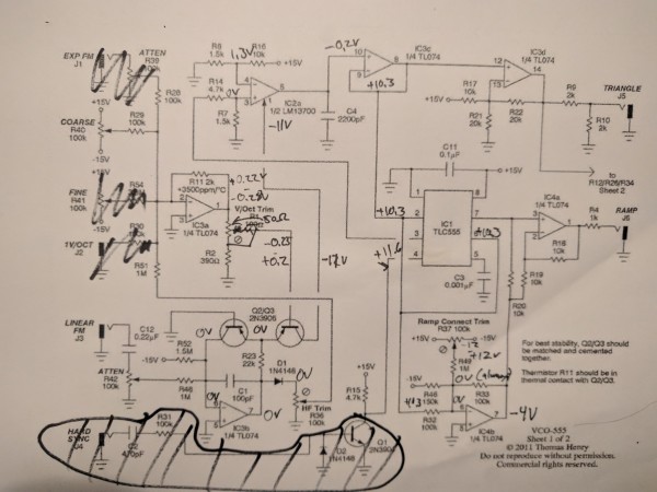
pin 2 on IC 3a may be considered as a "virtual earth summing point" of the inverting amp built with it (http://www.electronics-tutorials.ws/opamp/opamp_2.html)
so that being (around) 0V should be OK.
That being said, I am surprised by the -3.3 V at the pin 6, since IC 3b is also an inverting amp |
|
|
Back to top
|
|
|
hedefalk
Joined: Aug 29, 2017
Posts: 51
Location: Stockholm, Sweden
|
| Posted: Wed Aug 30, 2017 4:28 am Post subject:
|
|
|
Thanks!
Yes, I realised this later on that pin 2 on IC 3A would be pushed towards ground by the feedback resistor, was a bit tired there after troubleshooting several hours and I'm just learning about all this 
By twisting the Coarse pot I can get from -0.3V to +0.25V on IC3A output pin 1.
IC3B pin 6 is actually around -3.8V now (I've twisted pots and exchanged the 3906:s so maybe because of that)
>That being said, I am surprised by the -3.3 V at the pin 6, since IC 3b is also an inverting amp
Could you elaborate on that? I'm still trying to understand how this circuit should work
There's around 10V on the output from that opamp, but there's a cap going from the output to the inverting input so no DC coming through there. |
|
|
Back to top
|
|
|
hedefalk
Joined: Aug 29, 2017
Posts: 51
Location: Stockholm, Sweden
|
|
|
Back to top
|
|
|
translucent
Joined: Sep 29, 2006
Posts: 8
Location: the Netherlands
|
| Posted: Wed Aug 30, 2017 6:24 am Post subject:
|
|
|
| hedefalk wrote: |
Could you elaborate on that? I'm still trying to understand how this circuit should work
There's around 10V on the output from that opamp, but there's a cap going from the output to the inverting input so no DC coming through there. |
The DC current flows through R23 and Q2, by the way since this is a PNP transistor with the base at 0 V, the emitter should measure something like + 0.7 V, so the -10.5 V also surprises me |
|
|
Back to top
|
|
|
gdavis
Joined: Feb 27, 2013
Posts: 359
Location: San Diego
Audio files: 1
|
| Posted: Wed Aug 30, 2017 8:34 pm Post subject:
|
|
|
| hedefalk wrote: | Ngh!
After doing more and more troubleshooting and exchanging components to see if anything was borked, I now have something entirely different and no oscillation from the 555 at all: |
Check IC3 and it's connections. Pins 8, 9 and 10 should all be the same voltage.
_________________
My synth build blog: http://gndsynth.blogspot.com/ |
|
|
Back to top
|
|
|
fonik

Joined: Jun 07, 2006
Posts: 3950
Location: Germany
Audio files: 23
|
| Posted: Thu Aug 31, 2017 12:39 am Post subject:
|
|
|
| hedefalk wrote: | | Could you elaborate on that? I'm still trying to understand how this circuit should work |
as i see it this is a clever approach of the classic integrator(IC2A)/comparator(IC3C) VCO with C4 being the timing cap, only that the switching is done by the 555 (ISO a JFET).
BTW how did you measure the voltages? It would not make much sense to measure the voltage with a DMM at pins IC3C/p8&9 and IC1/p2&6 since this is where the actual core oscillation happens. Or do you have a scope for the measurements?
_________________

cheers,
matthias
____________
Big Boss at fonitronik
Tech Buddy at Random*Source |
|
|
Back to top
|
|
|
alanwilder81
Joined: Sep 03, 2016
Posts: 310
Location: italy
|
| Posted: Thu Aug 31, 2017 1:26 am Post subject:
|
|
|
hey mattias
i am trying to make sense of my 555 VCO ouput levels.
Why can't AC saw,tri, square and sin be measured with a DMM ?
I do have an old scope, but the grid doesn't show numbers nor reference points to get a quantitative measurement.
I can only observe a consistent waves ampliture across the whole frquency spectrum, yet, if the voltages are measured with th DMM ,they considerably vary from 2 V to 4 V roughly  |
|
|
Back to top
|
|
|
fonik
Joined: Jun 07, 2006
Posts: 3950
Location: Germany
Audio files: 23
|
| Posted: Thu Aug 31, 2017 2:17 am Post subject:
|
|
|
| alanwilder81 wrote: | hey mattias
i am trying to make sense of my 555 VCO ouput levels.
Why can't AC saw,tri, square and sin be measured with a DMM ? |
it could, but what would the reading tell you? you would see the RMS reading, however, you could not tell if there is an oscillation or not.
my idea is: maybe one cannot hear the VCO module on it´s actual outputs because there is something wrong between the core and the outputs. i would start from the inside to the outside and make sure that the core is working.
_________________
cheers,
matthias
____________
Big Boss at fonitronik
Tech Buddy at Random*Source |
|
|
Back to top
|
|
|
hedefalk
Joined: Aug 29, 2017
Posts: 51
Location: Stockholm, Sweden
|
| Posted: Thu Aug 31, 2017 2:25 am Post subject:
|
|
|
| gdavis wrote: |
Check IC3 and it's connections. Pins 8, 9 and 10 should all be the same voltage. |
They are not. non-inverting input (pin 10 is negative close to ground, -0.2V and and 8, 9 (output and inverting input) are saturated pos on around +10.3V it seems. Why should they be the same? There's no feedback resistor?
This circuit is really hard to understand for me, I guess it was probably not the best thing to start with as a newb |
|
|
Back to top
|
|
|
fonik
Joined: Jun 07, 2006
Posts: 3950
Location: Germany
Audio files: 23
|
| Posted: Thu Aug 31, 2017 2:30 am Post subject:
|
|
|
you read my post above?
_________________
cheers,
matthias
____________
Big Boss at fonitronik
Tech Buddy at Random*Source |
|
|
Back to top
|
|
|
hedefalk
Joined: Aug 29, 2017
Posts: 51
Location: Stockholm, Sweden
|
| Posted: Thu Aug 31, 2017 2:33 am Post subject:
|
|
|
| fonik wrote: | | hedefalk wrote: | | Could you elaborate on that? I'm still trying to understand how this circuit should work |
as i see it this is a clever approach of the classic integrator(IC2A)/comparator(IC3C) VCO with C4 being the timing cap, only that the switching is done by the 555 (ISO a JFET).
BTW how did you measure the voltages? It would not make much sense to measure the voltage with a DMM at pins IC3C/p8&9 and IC1/p2&6 since this is where the actual core oscillation happens. Or do you have a scope for the measurements? |
I'm using this cheap ebay 18$ digital scope. I actually bricked my multimeter so I'm only using that scope to measure everything.
I HAD oscillation at one point on these pins but at 47kHz (could this be what a saturated +12V CV would give?) but at this point I have no oscillation, but around +10V constant. |
|
|
Back to top
|
|
|
fonik
Joined: Jun 07, 2006
Posts: 3950
Location: Germany
Audio files: 23
|
| Posted: Thu Aug 31, 2017 3:12 am Post subject:
|
|
|
are you powering this circuit from 12V or from 15V?
measuring the voltage on the control pin of the OTA is not that simple. this input is a current input. it normally sits on the negative supply and should go up just a little bit when you feed this circuit a CV.
anyways, maybe you should start from scratch with just the OTA, IC3C and the 555.
leave off the expo for a start, just connect a 100k pot (between +V and -V)with wiper via 56k to the OTAs control input.
_________________
cheers,
matthias
____________
Big Boss at fonitronik
Tech Buddy at Random*Source |
|
|
Back to top
|
|
|
hedefalk
Joined: Aug 29, 2017
Posts: 51
Location: Stockholm, Sweden
|
| Posted: Thu Aug 31, 2017 3:19 am Post subject:
|
|
|
| fonik wrote: | are you powering this circuit from 12V or from 15V?
measuring the voltage on the control pin of the OTA is not that simple. this input is a current input. it normally sits on the negative supply and should go up just a little bit when you feed this circuit a CV.
anyways, maybe you should start from scratch with just the OTA, IC3C and the 555.
leave off the expo for a start, just connect a 100k pot (between +V and -V)with wiper via 56k to the OTAs control input. |
I'm using 12V (eurorack)
Thanks, I'll try that! Sorry if stupid question, but that's the amp bias input you mean on the OTA? Pin 1? |
|
|
Back to top
|
|
|
fonik
Joined: Jun 07, 2006
Posts: 3950
Location: Germany
Audio files: 23
|
| Posted: Thu Aug 31, 2017 3:27 am Post subject:
|
|
|
yes, pin1.
and if you measured -12V on the OTAs pin1 then this is the negative supply. i think it is a safe bet that you either got no control voltage/current to this pin (see my post above), or that your OTA is fried.
pin1 (pin 16 resp) sitting on the negative supply no matter what you do is a safe sign for a dead LM13700.
_________________
cheers,
matthias
____________
Big Boss at fonitronik
Tech Buddy at Random*Source |
|
|
Back to top
|
|
|
alanwilder81
Joined: Sep 03, 2016
Posts: 310
Location: italy
|
| Posted: Thu Aug 31, 2017 3:58 am Post subject:
|
|
|
thanks Mattias,
I can hear my VCO oscillating and sounds awesome.
The waves look perfect on the scope.
i am trying to find a way to measure their amplitude.
and trying to understand why, when sweeping the coarse tune knob, my regular DMM reads a voltage fluctuation, while the oscilloscope shows a perfectly consistent amplitude
so , i believe DMM is not right to measure AC ?
cheers |
|
|
Back to top
|
|
|
hedefalk
Joined: Aug 29, 2017
Posts: 51
Location: Stockholm, Sweden
|
| Posted: Thu Aug 31, 2017 3:59 am Post subject:
|
|
|
I'm more and more expecting these cheap Chinese breadboards I'm using…
And yes the OTAs pin 1 stays at -12V no matter what. I'm into my third LM13700, I'll try one more (only have 5) before I rebuild from scratch. Not good if my current setup is instantly frying those chips
I did what you suggested with the current one though. I have triangle oscillation in OTA pin 5. YEY! And I can control the frequency with the 100k pot. I'll probably just sit here and twist that knob all day - this is the first time I've heard anything, been just watching that scope for a few days
Still, the OTA pin1 is constant -12V. So the voltage drop over the 56k resistor is the whole diff between anything I turn the pot voltage divider to. Anything from -12 to +12 and the other side of the resistor is still -12K. You sure about the OTA being dead then?
By the way, when I probe pin 1 with the scope, the tone rises a couple of octaves - I guess the scopes impedance isn't very high? Or is this just the case since this is a current input?
Thanks a lot for all the help |
|
|
Back to top
|
|
|
alanwilder81
Joined: Sep 03, 2016
Posts: 310
Location: italy
|
| Posted: Thu Aug 31, 2017 4:15 am Post subject:
|
|
|
and thanks foe explaining the topology of the VCO.
so the core can be narrowed down to the mere 13700, 555 and IC 3 c ?
how do i go if i want to leave out the hard sync ? leave the 555 pin 4 unconnected ? |
|
|
Back to top
|
|
|
fonik
Joined: Jun 07, 2006
Posts: 3950
Location: Germany
Audio files: 23
|
| Posted: Thu Aug 31, 2017 4:18 am Post subject:
|
|
|
| hedefalk wrote: | | I did what you suggested with the current one though. I have triangle oscillation in OTA pin 5. YEY! And I can control the frequency with the 100k pot. I'll probably just sit here and twist that knob all day - this is the first time I've heard anything, been just watching that scope for a few days |
now this is a starting point, isn't it?
so you just have to re-build the expo section now. make sure that you have the transistors in the correct pinout and orientation. if you are in doubt refer to the datasheet, or take a look here:

| Quote: | | Still, the OTA pin1 is constant -12V. So the voltage drop over the 56k resistor is the whole diff between anything I turn the pot voltage divider to. |
the 56k converts the voltage to a current that is suitable for the OTA (Ohm's Law). remember, the OTAs bias input works with current, not with voltage.
| Quote: | | Anything from -12 to +12 and the other side of the resistor is still -12K. You sure about the OTA being dead then? |
IIRC one expects just a tiny change in the mV range. maybe you simply cannot see it on the scope with the current setting.
_________________
cheers,
matthias
____________
Big Boss at fonitronik
Tech Buddy at Random*Source |
|
|
Back to top
|
|
|
fonik
Joined: Jun 07, 2006
Posts: 3950
Location: Germany
Audio files: 23
|
| Posted: Thu Aug 31, 2017 4:21 am Post subject:
|
|
|
| alanwilder81 wrote: | and thanks foe explaining the topology of the VCO.
so the core can be narrowed down to the mere 13700, 555 and IC 3 c ?
how do i go if i want to leave out the hard sync ? leave the 555 pin 4 unconnected ? |
do as hedefalk did, use the 4k7 (R15) pull-up resistor.
_________________
cheers,
matthias
____________
Big Boss at fonitronik
Tech Buddy at Random*Source |
|
|
Back to top
|
|
|
fonik
Joined: Jun 07, 2006
Posts: 3950
Location: Germany
Audio files: 23
|
| Posted: Thu Aug 31, 2017 4:24 am Post subject:
|
|
|
| alanwilder81 wrote: | thanks Mattias,
I can hear my VCO oscillating and sounds awesome.
The waves look perfect on the scope.
i am trying to find a way to measure their amplitude.
and trying to understand why, when sweeping the coarse tune knob, my regular DMM reads a voltage fluctuation, while the oscilloscope shows a perfectly consistent amplitude
so , i believe DMM is not right to measure AC ?
cheers |
a DMM has a ~V function, however, it does not help, when you even don't know if it oscillates at all.
i use my scope to measure the amplitude. for our simple synth DIY tasks a cheap USB scope is enough, i believe.
_________________
cheers,
matthias
____________
Big Boss at fonitronik
Tech Buddy at Random*Source |
|
|
Back to top
|
|
|
|

 Forum index » DIY Hardware and Software » Thomas Henry designs