Posted: Sun Jun 21, 2020 8:05 am Post subject:
Video Series: DIY Analog VCO Subject description: How to build a v/oct analog oscillator from scratch
hi all,
I've started a new video series on how to build a v/oct analog VCO. here's the first part, where I go over the oscillator core and explain what all the components do in detail:
Joined: Jan 14, 2010 Posts: 5794 Location: Moon Base
Audio files: 709
Posted: Mon Jun 22, 2020 4:13 am Post subject:
great video! I like the balloon analogy
And now I need to do an experiment myself because I was expecting the waveform to be much more curved.
So I wonder if that is caused by the resistor to GND (I would have connected it between in and output) or a result
of the schmitt trigger (doubtful). _________________ "My perf, it's full of holes!" http://phobos.000space.com/ SoundCloudBandCampMixCloudStickney SynthyardsCaptain ColliderTwitchYouTube
Yeah nice movie, at first I was very sceptical about the anologies used .. and then was surprised by the balloon too
PHOBoS wrote:
So I wonder if that is caused by the resistor to GND (I would have connected it between in and output) or a result
of the schmitt trigger (doubtful).
Maybe the latter yeah .. the signal does not travel full range .. but it should still be part of an expo curve .. unless the schmitt trigger is implemented by feeding back directly to the input .. erm .. well ... a bit of the output is seen at the physical input ... could test that driving the gate with a resistor with a saw or tri wave.
Anyway .. also thought it to look remarkably flat.
Edit: there is some theory about such anologies .. it was something with Tensor and Flow iirc .. but I see Google to seem to have hijacked the terms for something deep learning ...
edit2: ah .. was wrong .. bond graphs it was .. with Flow and Effort ... https://en.wikipedia.org/wiki/Bond_graph _________________ Jan
also .. could someone please turn down the thermostat a bit.
Joined: Jan 14, 2010 Posts: 5794 Location: Moon Base
Audio files: 709
Posted: Mon Jun 22, 2020 7:28 am Post subject:
Blue Hell wrote:
the signal does not travel full range .. but it should still be part of an expo curve
yeah, now that I am a bit more awake it does make sense. I was thinking it doesn't matter what voltage you use to charge
the capacitor, ie 5V or 10V the cap doesn't care and the curve would look the same. But of course in this case the voltage it
gets charged with is higher than the treshold voltage at which the schmitt trigger stops the charging. And of course this goes
for discharging aswell so you cut of the top and bottom of the expo curve and then it looks a lot more linear. It's still less curved
than I was expecting though.
Joined: Jan 14, 2010 Posts: 5794 Location: Moon Base
Audio files: 709
Posted: Mon Jun 22, 2020 1:36 pm Post subject:
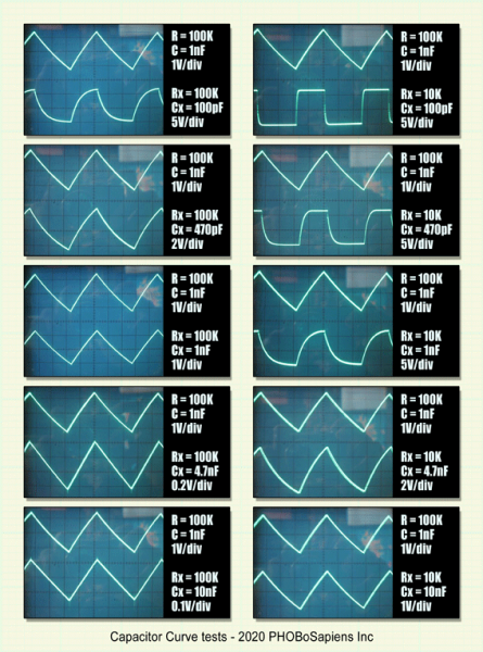
I did some tests driving an RC filter with the output of the oscillator to see if that would give somewhat different results,
spoiler: it doesn't. Of course I couldn't use a sawtooth oscillator as that would result in a squarewave output with a dutycycle
close to 0% or 100% depending on the direction of the diode. I tested with some different capacitor and resistor values and
the results aren't really surprising, as a matter of fact they are as expected.
The curve of Rx=10K/Cx=470pF, Rx=10K/Cx=4.7nF is more in line with how I thought it would look. This makes sense as
the window of the schmitt trigger is actually much smaller than I thought. With a 12V supply the amplitude of the voltage
over C seems to be only about 2.75V.
CCT1.png
Description:
Filesize:
64.46 KB
Viewed:
404 Time(s)
This image has been reduced to fit the page. Click on it to enlarge.
CCT2.png
Description:
Filesize:
222.88 KB
Viewed:
388 Time(s)
This image has been reduced to fit the page. Click on it to enlarge.
ha, you got me! nice analysis PHOBoS. yeah the wave is definitely not clean. I was surprised myself that I could get the oscillator to stay in tune over 5 octaves. but I think that makes it a very nice, rewarding first build for complete beginners.
Joined: Jan 14, 2010 Posts: 5794 Location: Moon Base
Audio files: 709
Posted: Tue Jun 23, 2020 2:58 pm Post subject:
fosimoor wrote:
ha, you got me! nice analysis PHOBoS. yeah the wave is definitely not clean. I was surprised myself that I could get the oscillator to stay in tune over 5 octaves. but I think that makes it a very nice, rewarding first build for complete beginners.
I was just curious why it looked so straight. Wondering if somehow the schmitt trigger had some weird linearizing effect.
But it's just due to only using a small section of the expo curve which looks rather straight. Just using the oscillator to drive
an RC network with similar values would have been enough as it shows that the result is pretty much identical but I got curious
about what would happen with different values. If you make the values larger you get an even straighter shape but at a lower
amplitude. Note that for the oscillator itself it shouldn't make a difference what values you choose, the shape remains the same
and it doesn't have any influence on the tracking.
good to know that it doesn't negatively affect the tracking! here's the next episode:
i hope my BJT explanation isn't too far off. it's been consistent with my experiments though. when i swap the 2.2 nF cap for a 10 uF one (and the 100k drain resistor for a 2k), the wave becomes really curved and wonky, which is in line with PHOBoS' experiments i think!
next up is getting rid of temperature dependence, fixing the scaling and possibly some waveshaping to get a variable pulse wave!
You cannot post new topics in this forum You cannot reply to topics in this forum You cannot edit your posts in this forum You cannot delete your posts in this forum You cannot vote in polls in this forum You cannot attach files in this forum You can download files in this forum

 Forum index » How-tos