| Author |
Message |
Steve_the

Joined: Sep 28, 2023
Posts: 3
Location: Texas, United States
|
 Posted: Thu Sep 28, 2023 8:44 am Post subject: Posted: Thu Sep 28, 2023 8:44 am Post subject:
 Issues constructing Reverse Avalanche Oscillators. Issues constructing Reverse Avalanche Oscillators. |
  |
|
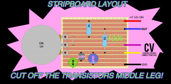
As an easy first project I was recommended to try a Reverse Avalanche Oscillator. Under even modest scrutiny they aren’t great, but even with an additional OPamp/Tl702 per so it will output usable CV (as shown in the first attached schematic) they should be very cost effective and simple to construct. My plan was to stick about three of them into an ~8HP plate as a “Drone/Chorus/Better than no LFO’s” module and I got invested in the idea.
The problem is I’m too dense to get one working and now I’m afraid to move on to something more sophisticated until I figure this out.
So far I’ve been following the attached schematics with little success, even swapping the N2904/BC337’s with S9018’s as is recommended by LMNC in his later versions and this paper: http://www.kerrywong.com/2014/03/19/bjt-in-reverse-avalanche-mode/ I’ve been having constant issues getting the core oscillating on a breadboard. The best I got was yesterday afternoon, where I could get a single brief pulse when connecting the power supply, and that pulse couldn’t even drive an 8Omh speaker. A friend of mine was able to get them working just fine at 13.3v but all I've got to run the entire synth is a 12v 2A wall wart, and all the schematics I've seen so far are supposed to be fine at 9-12v.
It’s been really frustrating failing to get what’s supposed to be such a simple circuit running this week. If you have any tips, tricks, or hopefully a better schematic please share them.
| Description: |
| Credit to: Kristian Blåsol |
|
| Filesize: |
78.58 KB |
| Viewed: |
148 Time(s) |
| This image has been reduced to fit the page. Click on it to enlarge. |

|
| Description: |
| Credit to: LMNC (Look Mum No Computer) |
|
| Filesize: |
126.22 KB |
| Viewed: |
109 Time(s) |
| This image has been reduced to fit the page. Click on it to enlarge. |
|
_________________
"Bernard of Chartres used to compare us to dwarfs perched on the shoulders of giants. He pointed out that we see more and farther than our predecessors, not because we have keener vision or greater height, but because we are lifted up and borne aloft on their gigantic stature." ~John of Salisbury 1159
Last edited by Steve_the on Thu Sep 28, 2023 9:57 pm; edited 1 time in total |
|
|
Back to top
|
|
 |
blue hell
Site Admin

Joined: Apr 03, 2004
Posts: 24388
Location: The Netherlands, Enschede
Audio files: 296
G2 patch files: 320
|
| Posted: Thu Sep 28, 2023 12:21 pm Post subject:
|
|
|
Hi Steve,
Welcome 
- For the tl072 to work you will need a bipolar power suppy - you did not mention that you use that.
- An 80 Ohm speaker connected directly does not seem like a good idea - on the buffered output it might need a series resistor of 200 Ohm or so (and it may be soft then) - on the unbuffered output it will not work at all. Better it would be to make a little audio amplifier for driving the speaker.
_________________
Jan
also .. could someone please turn down the thermostat a bit.
 |
|
|
Back to top
|
|
|
Steve_the
Joined: Sep 28, 2023
Posts: 3
Location: Texas, United States
|
| Posted: Thu Sep 28, 2023 2:12 pm Post subject:
|
|
|
| Quote: | | - Welcome |
Glad to be here!
| Quote: | | - For the tl072 to work you will need a bipolar power supply - you did not mention that you use that. |
I did not, I will however get one. If you don't mind me asking, would a generic 12v switching power supply with a Pos,Neg,and ground terminal such as attached image be appropriate/is there more to a bipolar supply than that, if so what should I look for and approximately what amperage and wattage?
| Quote: | | - An 80 Ohm speaker connected directly does not seem like a good idea |
That was a bit of bad typing on my part, it was only an 8 Ohm and it's broken. I am unsure if it was broken when first I salvaged it or when one of my circuits killed it but it's certainly dead now.
| Description: |
| 12V 5A 60W Power Supply, I am unsure if it qualifies as bipolar. |
|
| Filesize: |
35.86 KB |
| Viewed: |
3581 Time(s) |

|
_________________
"Bernard of Chartres used to compare us to dwarfs perched on the shoulders of giants. He pointed out that we see more and farther than our predecessors, not because we have keener vision or greater height, but because we are lifted up and borne aloft on their gigantic stature." ~John of Salisbury 1159 |
|
|
Back to top
|
|
|
blue hell
Site Admin
Joined: Apr 03, 2004
Posts: 24388
Location: The Netherlands, Enschede
Audio files: 296
G2 patch files: 320
|
| Posted: Thu Sep 28, 2023 3:22 pm Post subject:
|
|
|
Re. the switching power supply
.. I can not tell from the image alone what it does, it would need specifications to be sure .. but I'd assume it to be a single supply where by putting a link from +V or -V to ground you can make it a positive or a negative supply ... which in turn would mean that you could use two to make a dual supply ..
.. But then ... 60 Watt .. this means 5 Amp at 12V (p=V.I or power is voltage times current) and that is is a bloody lot in case things go wrong (like an IC connected wrongly or inserted backwards) and it migh launch parts into the ceiling .. but hey .. that happened to me only once .. at least things will be immediately clear then :)
.. Idealy for experimenting you would want a power supply for which you can limit the curent to about what is to be expected to be needed for the circuit. This will take some budget ... like a lab supply .. and for analog use that should be a dual supply with voltage control and current limiting ... but eh .. I've known times without budget .. and I dont know about yours .. but a low cost alternative would be to construct something that has less power for experimenting, maybe wallwart based, there are curcuits around for that on the web. Otoh .. when you buy a scope you may be able to afford a lab supply :)
.. Then, when the test thingie works and did not go up in smoke you could be confident to trust it to a bigger supply. Some people frown on switching supplies, but I think that not to be an issue nowadays ... and when it is does turn out to be an issue there are ways to solve it. With time you'll form you own opinion there :)
.. I guess you already have some volt / ampere / ohm meter -- and if not, you'll want someting for that . don't go expensive on that until you know why you'd need that .. you'll go trough a few while learning.
_________________
Jan
also .. could someone please turn down the thermostat a bit.
|
|
|
Back to top
|
|
|
Steve_the
Joined: Sep 28, 2023
Posts: 3
Location: Texas, United States
|
| Posted: Thu Sep 28, 2023 9:55 pm Post subject:
|
|
|
Thank you again for the tips! I'll be having to stick with a wallwart for a while anyways as I already burnt the last of my budget on a cheapo scope.
I did manage to get the circuit working too by cycling through a few transistors, it turns out the real issue was that cheap transistors I got off ebay aren't very reliable.
At the very least I'm glad I was informed about power supplies before I blew up some OPamps or my heart.
_________________
"Bernard of Chartres used to compare us to dwarfs perched on the shoulders of giants. He pointed out that we see more and farther than our predecessors, not because we have keener vision or greater height, but because we are lifted up and borne aloft on their gigantic stature." ~John of Salisbury 1159 |
|
|
Back to top
|
|
|
Grumble
Joined: Nov 23, 2015
Posts: 1310
Location: Netherlands
Audio files: 30
|
| Posted: Thu Sep 28, 2023 11:09 pm Post subject:
|
|
|
First thing I noticed when glancing over the schematic is the 100k pot at the cv input.
This is far to large impedance since it is in series with the led(s)
Why don’t you use the spare opamp to buffer the cv in?
_________________
my synth |
|
|
Back to top
|
|
|
blue hell
Site Admin
Joined: Apr 03, 2004
Posts: 24388
Location: The Netherlands, Enschede
Audio files: 296
G2 patch files: 320
|
| Posted: Fri Sep 29, 2023 3:00 am Post subject:
|
|
|
| Steve_the wrote: | | I did manage to get the circuit working too by cycling through a few transistors, it turns out the real issue was that cheap transistors I got off ebay aren't very reliable. |
Heh, it is more that the circuit is not reliable though 
The thing is, and I should have said this earlier, the transistor is used in an out of spec way in this circuit.
It is not that it will not work, just that the voltage at wich it will break trough is not well defined and it is not being tested for in production.
Also it is not that the circuit is bad, it is a design idea, and all design ideas have consequences (like working better to specs, being more reliable, being cheaper or more practical .. whatever).
You'll see this same construction in noise generating circuits, and usually you will have to go trough a handful of transistors to find one which works to satisfaction.
The table with voltages on the web site ( http://www.kerrywong.com/2014/03/19/bjt-in-reverse-avalanche-mode/ ) must not be seen as a specification but more like a set of examples - you will find different voltages for the same type of transistor and the values can vary quite a bit .. athough a value like 12V or so is not unusual.
Anyway, good you found a transistor that works 
_________________
Jan
also .. could someone please turn down the thermostat a bit.
|
|
|
Back to top
|
|
|
|

 Forum index » DIY Hardware and Software
