Joined: Mar 28, 2006 Posts: 1472 Location: Kansas City, Mo USA
Audio files: 45
Posted: Thu Jan 25, 2024 4:37 pm Post subject:
2024 Build Pictures Subject description: Share your DIY project pictures here!
Hello to all.
I recently encountered a challenge with my setup involving the Looperlative LP1 and my modular synthesizer, prompting me to devise a solution in the form of a utility module.
For years, I've relied on the LP1 looper as a solid MIDI Clock source for my modular synth. One issue I faced was ensuring precise clock message divisions without any timing discrepancies. Additionally, I needed to maintain synchronization between my sequencers and the LP1.
Initially, I capitalized on a unique behavior of the LP1, wherein it sent a MIDI START message at the conclusion of the master clock loop. This served as a convenient trigger to reset my clock dividers and sequencers on the modular.
However, after updating the LP1's software, this handy "quirk" vanished. Fortunately, the LP1's creator, Bob, introduced a new feature. Users could now signal the LP1 with a custom program change message, prompting the LP1 to output the RESET message at the end of the master loop.
To retain the functionality of the original "quirk," my utility module comes into play. It monitors the MIDI message stream from the LP1 and, upon detecting a MIDI RESET, automatically dispatches the necessary Program Change message to the LP1. Thankfully, my FCB1010 controller, used to manage the LP1, conveniently passes its MIDI IN to its MIDI OUT.
Looking ahead, I have more Arduino projects lined up for this year. Specifically, I'm planning to develop quantizers and additional control circuits tailored for the modular synth.
LP1ClockMod02.jpg
Description:
Utility module to force the LP1 to send a MIDI Reset at the end of the master clock loop (cover removed).
Filesize:
6.42 MB
Viewed:
237 Time(s)
This image has been reduced to fit the page. Click on it to enlarge.
LP1ClockMod01.jpg
Description:
Utility module to force the LP1 to send a MIDI Reset at the end of the master clock loop.
Filesize:
8.55 MB
Viewed:
259 Time(s)
This image has been reduced to fit the page. Click on it to enlarge.
_________________ -- Kevin http://kevinkissinger.com Last edited by kkissinger on Fri Jan 26, 2024 8:16 am; edited 1 time in total
Posted: Sun Feb 18, 2024 3:38 am Post subject:
Oberheim SEM LFO submodule in SMT Subject description: First feasibility evaluation of a SEM clone in SMT
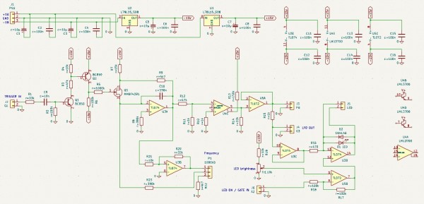
This is my first pure SMT finger exercise (beside one diode 1N4148). I thought cloning an Oberheim SEM would be a nice project for SMT training. I started with a rather simple sub project of the SEM, the LFO. Though rather easy, it has some functional specials for being integral part of a / my SEM:
1.) (Re-)Trigger(able): The LFO starts in a defined state when triggered. This can be used to sync several LFOs within a 2-, 4- or 8-voice instrument.
2.) Monitoring LED on front panel: Follows the LFO signal
3.) Monitoring LED on PCB: For debugging purposes
4.) Gate indicator: The LFO activity (on board and front panel) is only visible if the LFO is accessed by a GATE signal. This shows more clearly that the SEM is invoked in a polyphonic context.
First, as in most Analogmonster projects, I made extensive spice simulations, especially as I changed some components into SMT variants:
1.) I replaced the n-channel-fet of the original circuit by the SMT MMBF4391-ONS transistor.
2.) I replaced the 741 opamp (only available in SOP) by the TL071 (available in SO-8 as well). In fact I used a TL074 and a TL072 in SO-8 as I needed more opamps for the "special" functions.
3.) I used the LM13700 as replacement for the CA3080 of the original, as the CA3080 is not available as SMD.
3_CircuitKiCad.jpg
Description:
KiCad schema
Filesize:
142.98 KB
Viewed:
250 Time(s)
This image has been reduced to fit the page. Click on it to enlarge.
4_Screenshot 2024-02-18 111348.jpg
Description:
LTSpice analysis: LFO out (V(g3)), Gate (V(x2)), Trigger (V(g1)), LED current (I(D1))
Filesize:
490.8 KB
Viewed:
235 Time(s)
This image has been reduced to fit the page. Click on it to enlarge.
5_Screenshot 2024-02-14 082226.jpg
Description:
Board
Filesize:
155.59 KB
Viewed:
207 Time(s)
This image has been reduced to fit the page. Click on it to enlarge.
Your SMT PCB is impressive! Where do you get SMT training? (I have a workstation but it came with no instructions on how to set the temps on it.)
Congrats on your project.
Thanks, but at the end I just tried it. YouTube was not really a help for me. Some say "not more than 300 degrees Celsius", others say "normal temperature, but less time", some say "use a special soldering equipment", others say "you can use your standard iron", so at the end I was quite confused
300 degrees was much too low. Nothing was melting Finally I used my "standard" temperature of 400 degrees Celsius and my standard iron, taking into consideration that my first SMT exercise would be fried, but nothing bad happened at all, everythink works fine, short solder time with high solder temperatures seems to be ok, so this is my recommendation for first tests. _________________ Analogmonster: https://www.analog-monster.de/index_en.html
YouTube: https://www.youtube.com/user/TheAnalogmonster
SoundCloud: https://soundcloud.com/analogmonster-1
Joined: Mar 28, 2006 Posts: 1472 Location: Kansas City, Mo USA
Audio files: 45
Posted: Wed Feb 28, 2024 4:03 am Post subject:
analogmonster wrote:
Finally I used my "standard" temperature of 400 degrees Celsius and my standard iron, taking into consideration that my first SMT exercise would be fried, but nothing bad happened at all, everythink works fine, short solder time with high solder temperatures seems to be ok, so this is my recommendation for first tests.
Really appreciate the information. Do you use a microscope or some kind of magnifier for SMT work? _________________ -- Kevin http://kevinkissinger.com
...
Do you use a microscope or some kind of magnifier for SMT work?
Yes, I do. For soldering of passive components like diodes, resistors or capacitors in 1206 size I use precision mechanic glasses (see below). This one magnifies factor 2.5. It can be adapted to the needs of your eyes (diopters) additionally.
For active components like transistors and integrated circuits (SO-8 size) I use a magnifying glass additionally (see below).
Feinmechanikerbrille.jpg
Description:
Precision mechanic glasses
Filesize:
151.63 KB
Viewed:
211 Time(s)
This image has been reduced to fit the page. Click on it to enlarge.
Lupe.jpg
Description:
Tool with magnifying glass
Filesize:
143.43 KB
Viewed:
208 Time(s)
This image has been reduced to fit the page. Click on it to enlarge.
Posted: Mon Mar 04, 2024 7:59 am Post subject:
Oberheim SEM ENV submodule in SMT Subject description: Next feasibility evaluation of a SEM clone in SMT
Ok, after finalizing the SEM LFO I continued with the next SEM submodule, the envelope (ENV). There are two of them in each SEM.
It is a bit more complex than the SEM LFO, but being the second finger exercise it was a bit easier to build. And again, I found differences compared to other ADSR modules (envelopes) I built before.
First of all: It is not really an ADSR. There is a RELEASE phase of course, but it is more an ADS than an ADSR, as the RELEASE time can't be leveled by a pot. It depends from the SUSTAIN level.
Second: There are two time setting input signals instead of one: TRIGGER *and* GATE (in other ENV modules only GATE is used).
TRIGGER-only works; in this case the SEM ENV works as AR module. GATE-only does *not* work, as there is no envelope created without TRIGGER.
TRIGGER *and* GATE let the SEM ENV work as ADS(R) module, only then you can determine a SUSTAIN level by leveling it with the SUSTAIN pot.
Third: The SEM ENV is a Moog (tm) native speaker. It is able to process Moog S/TRIG events as well, not only positive voltage TRIGGER and GATE inputs.
So in total the SEM ENV is the second surprise in my SEM clone project. It can create very snappy envelopes for cool percussive effects, and if you use square LFOs with different frequencies as GATE and TRIGGER input, you get quite weird repetitive envelopes beside the standard ones (see video).
Again I did extensive spice analysis before building that thing. Find below the pictures, graphs and videos.
And again I added an onboard LED for debugging purposes.
SEM_ADSR_LTSpice.jpg
Description:
SEM ENV as ADS(R): SUSTAIN stage is added by GATE input. V(c) (green): TRIGGER input, V(a) (blue): GATE input, V(x1) (red): ENV output
Filesize:
325.79 KB
Viewed:
234 Time(s)
This image has been reduced to fit the page. Click on it to enlarge.
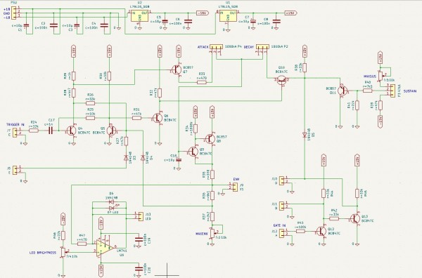
ENV_Circuit_KiCad.jpg
Description:
SEM ENV schema (KiCAD)
Filesize:
180.55 KB
Viewed:
243 Time(s)
This image has been reduced to fit the page. Click on it to enlarge.
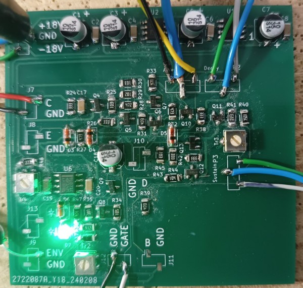
ENV_Board.jpg
Description:
SEM ENV as SMT
Filesize:
185.98 KB
Viewed:
191 Time(s)
This image has been reduced to fit the page. Click on it to enlarge.
Posted: Thu Mar 14, 2024 3:23 am Post subject:
Oberheim SEM VCA submodule in SMT Subject description: Next feasibility evaluation of a SEM clone in SMT
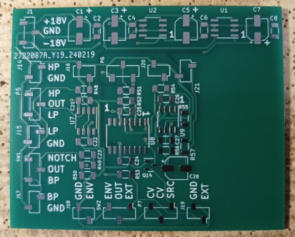
No. 3 of the Oberheim SEM submodules, the SEM VCA as SMT version, is up and running. And again I found some specials I don't know from other VCAs and which I consider as needed for integration aspects in the SEM environment.
The VCA core itself is absolute standard. An OTA based amplifier stage driven by a control voltage dependent current source. New for me was the source mixer onboard which does the job of a state variable VCF output selection and filter coupling (à là Moog 904-C filter coupler, see T904-C documentation). The other function I am wondering about is the voltage controlable DC offset setting. I know that the offset correction is needed for the specials of the SEM ENV output, but why voltage control? Perhaps someone can enlighten me.
Again I tried to be as close to the original as possible, but I had to do some changes for the SMT adaption:
1.) I replaced the CA3080 OTA by an LM13700, as no CA3080 exists as SMD
2.) I added an amplification level pot to avoid clipping due to external control voltages which are too high for the VCA
I integrated this test board into my Formant Modular environment and it works perfectly.
And again as always my offer: As JLCPCB always sends a minimum of 5 boards: If anybody wants to do own experiments or wants to build an own module from that board, contact me offlist.
The same for the other Analogmonster SEM SMT clone prototypes.
VCA_board.jpg
Description:
VCA board
Filesize:
156.09 KB
Viewed:
214 Time(s)
This image has been reduced to fit the page. Click on it to enlarge.
VCA_populated.jpg
Description:
Populated VCA board
Filesize:
214.75 KB
Viewed:
200 Time(s)
This image has been reduced to fit the page. Click on it to enlarge.
Joined: Mar 28, 2006 Posts: 1472 Location: Kansas City, Mo USA
Audio files: 45
Posted: Tue Aug 13, 2024 7:01 pm Post subject:
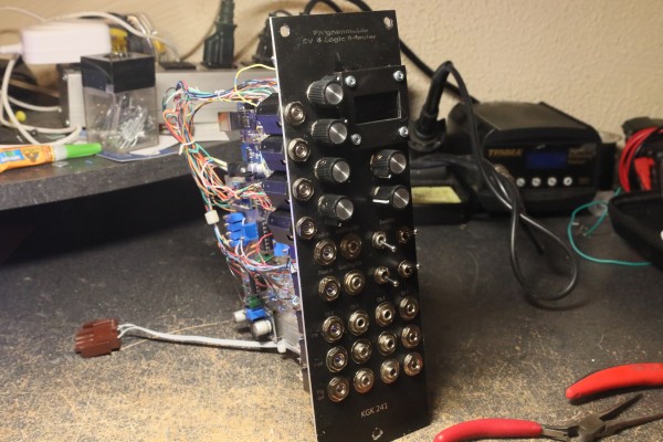
Programmable Control Voltage and Logic Adapter Subject description: Using an Arduino with the Modular Synthesizer
This module provides an interface between the Arduino's i/o and the synthesizer's i/o. The Arduino works with 5v Analog and logic levels and this module presents i/o to the synthesizer at 10v levels. The panel also has an OLED screen.
What the module does depends on the software I create for it! It is much easier to experiment with the module and software when it is mounted in the synthesizer. Thus, the non-application specific labeling and description.
The module (as configured) features the following:
(4) 16-bit Analog Inputs that handle from 0 to 8v
(4) 14-bit Analog Outputs that handle from 0 to 8v
(6) Logic output with 10v logic level (i.e., gates and triggers)
(2) Logic inputs that accept 10v logic levels
(4) Four 10-bit Analog Inputs with associated pots, normalled to 10v overridable via patch cord connections
(2) Control knobs (internal -- 0 to 5v -- they do not interface with synth but can be used to set non-cv parameters
(4) toggle switches (2 momentary contact)
(1) OLED screen
The 14-bit DAC provides 16,384 steps of resolution. Over eight volts (octaves) this resolves to .56 cent resolution which may exceed the accuracy of the analog VCO's anyway!
My original plan was to scale for an even 10v however there was noticeable noise when amplifying the DACS' outputs up to 10v. 8v was a good balance between noise and range. In addition to the scaling amplifier stage, I utilized a zero-gain buffer stage. This holds the output voltage constant despite the number of modules driven.
One of the issues when working with Arduinos is that they tend to "fry" when the logic levels are incorrect (particularly if a negative voltage appears on a logic pin). The module diode-protects the pins and separates them from the synthesizer levels via op-amp comparators.
The high-res analog inputs and outputs are designed to handle pitch-sensitive tasks. The low-res analog can handle Control voltages that don't demand the same level of precision.
The toggle switches are provided as another method to control the software.
OK, so what does it do? My current software project creates a quantizing sample/hold. The software supports two voltage maps that I call "scene-A" and "scene-B". The voltage maps correspond to different scales and tunings including non-quantization. A cross-fader allows gradual or rapid change between the scenes. A momentary-contact switch steps through various crossfade methods. Currently, I have an "average" method and a "wipe" method.
The "average" simply morphs from one table proportionally averaging the voltages based the control's position. The wipe selects scene-A or scene-B based on the control's position. In musical terms, if the pot is in the center position, all the notes from C to F are quantized with the scene-A table and F# through B from the scene-B table.
I am working on a common-tone method (that is, an intersection method). The idea is that the center position will give notes (voltages) that are common to both scenes. On positions left of center, the common tones plus notes unique to scene-A are presented, right of center introduces notes unique to scene-B. To program this method is a bit trickier than the first two methods!
Another feature of the software is that while it accepts a single input clock, the output produces clocks only when the voltage changes. I plan to make this a selectable feature and may provide internal clock dividers, etc.
I am using the four i/o clock lines as independent sample/holds.
However, what the module does is based on the programming. It could be configured as a CV looper, harmonizer, root-note calculator, etc. At this point, it is simply whatever I think up.
Anyway, I hope you enjoyed the technical notes here. I will post a video soon to demonstrate this -- forgive my slow pace for videos -- I am still trying to work out a few things with videos here.
0Q5A1447.JPG
Description:
Front Panel of CV and Logic Adapter
Filesize:
9.36 MB
Viewed:
225 Time(s)
This image has been reduced to fit the page. Click on it to enlarge.
0Q5A1448.JPG
Description:
PCB and Arduino for CV and Logic Adapter
Filesize:
10.7 MB
Viewed:
188 Time(s)
This image has been reduced to fit the page. Click on it to enlarge.
Posted: Wed Aug 14, 2024 2:16 am Post subject:
Re: Programmable Control Voltage and Logic Adapter Subject description: Using an Arduino with the Modular Synthesizer
kkissinger wrote:
...
What the module does depends on the software I create for it! It is much easier to experiment with the module and software when it is mounted in the synthesizer.
...
That's why I add an ISP interface to each and every module which operates with a microcontroller.
I really like the module and have used it quite a few times for electro-music streaming events.
blue hell wrote:
Quote:
Looks like there is voltage control for the quantizer steps & the fade etc. as well?
Also liked that sequencer idea - the knob seems to set the length?
Indeed, the parameters are voltage-controlled. I simply normalled 10v to the input plugs to enable the control knobs to work as you saw in the demo. With external cv's, the knobs would act as attenuators.
And actually, you inspired this because many of your Wren modules have similar functionality. In fact, one reason for this effort is to improve the ability to use Wren and the hardware synthesizer together. In the last few electro-music streaming events I have exploited the voltage-control in Wren to change tunngs on the fly. In particular, when I run with multiple instances of sequencers, to set all the temperaments from a single control makes things a lot easier. My ultimate direction is to utilize OSC so that I can better integrate Wren into my setup.
The fun thing about software is the ease of running with a new idea (on the fly) without having to design tons of hardware. Thus, the module -- currently running the sample/hold software, can just as easily be envelope generators, or melody generators, etc just based on the software.
Again, thanks to you both for checking out the demo video and taking the time to comment. _________________ -- Kevin http://kevinkissinger.com
My MODDER is an ESP32 based module to convert the input signal according to a chosen conversion.The input signal in this patch comes from the O&C module on the left (an Attack-Decay signal).
In this module is the conversion table visible in top part of the screen (horizontal the 8-bits input value, vertical the 8-bits output value)
The bottom half of the screen gives an indication of the input signal (amplitude versus time)
This module makes use of both cores of the ESP32, where one core only does the AD-conversion of the input signal, gets the conversion value to go with that signal and sends it to the DA-converter.
The other core controls the Oled screen and gets signals from the Rotary Encoder and does the calculation for the display.
The two potentiometers are the offset of the input signal and an attenuverter.
This module also works on audio signals up to a few kHz. _________________ my synth
Posted: Tue Sep 10, 2024 1:28 am Post subject:
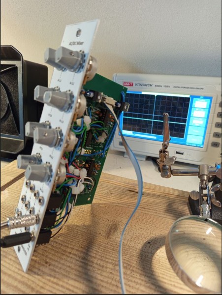
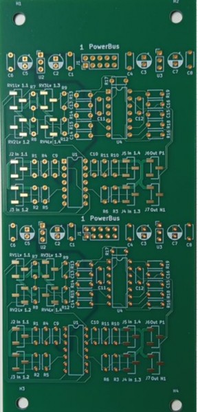
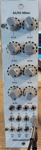
AC/DC Mixer Subject description: Helper module for the Analogmonster Modular
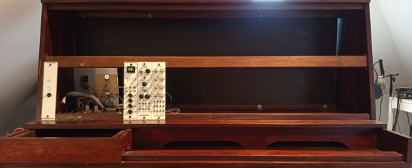
Not spectacular, but useful in any modular synthesizer (and I need this for mine): Two DC coupled 4 channel mixers with inverting and non-inverting outputs. It is part of my third modular:
Joined: Mar 28, 2006 Posts: 1472 Location: Kansas City, Mo USA
Audio files: 45
Posted: Wed Sep 25, 2024 5:01 am Post subject:
Grumble wrote:
My MODDER is an ESP32 based module to convert the input signal according to a chosen conversion.
I really like the functionality of your module. In fact, I may adapt your idea to my Arduino-based approach. What comes to mind is the idea that a single input voltage would be routed to multiple maps and a cross-fader could fade between maps. Also, you could map the same function to separate outputs at different phase positions.
Your output display is intuitive and very cool looking! _________________ -- Kevin http://kevinkissinger.com
My MODDER is an ESP32 based module to convert the input signal according to a chosen conversion.
I really like the functionality of your module. In fact, I may adapt your idea to my Arduino-based approach. What comes to mind is the idea that a single input voltage would be routed to multiple maps and a cross-fader could fade between maps. Also, you could map the same function to separate outputs at different phase positions.
Your output display is intuitive and very cool looking!
Thank you 😃👍🏻
This module is programmed using the Arduino IDE 😉 _________________ my synth
You cannot post new topics in this forum You cannot reply to topics in this forum You cannot edit your posts in this forum You cannot delete your posts in this forum You cannot vote in polls in this forum You cannot attach files in this forum You can download files in this forum

 Forum index » DIY Hardware and Software