| Author |
Message |
jhaible
Joined: May 25, 2007
Posts: 2014
Location: Germany
Audio files: 24
|
 Posted: Sun Feb 13, 2011 6:34 am Post subject: Posted: Sun Feb 13, 2011 6:34 am Post subject:
|
  |
|
| zarko wrote: | Hello Jürgen.
in my modular i have some attenuators pots, so i decided to omit the 10K log input pot, but the problem is that i can't leave the input aux without a jack plug in, if i don't do that i dsitoy my ears and speakers 
I try to solder a 10k resitor between ground and aux in but it's the same problem. For the moment i disconnect the comon of the feedback mode switch.
Would you tell me if there is an other solution to resolve this problem
without add a pot on the front panel because there is no place left.
Thank you.
Have a nice day.
Regards Fred. |
Make sure that the ccw end of the pot is grounded! - Then it should fully attenuate when in ccw position.
JH.
_________________
"I tell you the truth, if anyone says to this mountain, 'Go, throw yourself into the sea,' and does not doubt in his heart but believes that what he says will happen, it will be done for him. Therefore I tell you, whatever you ask for in prayer, believe that you have received it, and it will be yours." (Mk 11,23f) |
|
|
Back to top
|
|
 |
sduck

Joined: Dec 16, 2007
Posts: 459
Location: Nashville
Audio files: 5
|
| Posted: Sun Feb 13, 2011 8:12 pm Post subject:
|
|
|
| The wiring diagram as provided has a feedback circuit in it. If you delete the pot you've deleted an essential part of the feedback circuit. So yes, you'll need to disconnect the wire from the center of the feedback switch, and just do your feedback outside of the module if you choose to. The feedback circuit isn't essential to the operation of the frequency shifter, but it is a nice added touch. |
|
|
Back to top
|
|
|
jhaible
Joined: May 25, 2007
Posts: 2014
Location: Germany
Audio files: 24
|
| Posted: Mon Feb 14, 2011 12:42 am Post subject:
|
|
|
| sduck wrote: | | The wiring diagram as provided has a feedback circuit in it. If you delete the pot you've deleted an essential part of the feedback circuit. So yes, you'll need to disconnect the wire from the center of the feedback switch, and just do your feedback outside of the module if you choose to. The feedback circuit isn't essential to the operation of the frequency shifter, but it is a nice added touch. |
Thank you, sduck. I completely missed the part about the missing pot, and concluded there must be a mis-wired pot.
So, yes, it's all clear: You *need* that pot for proper feedback operation. But you can have a nice FS entirely without feedback also. Just what sduck says.
JH.
_________________
"I tell you the truth, if anyone says to this mountain, 'Go, throw yourself into the sea,' and does not doubt in his heart but believes that what he says will happen, it will be done for him. Therefore I tell you, whatever you ask for in prayer, believe that you have received it, and it will be yours." (Mk 11,23f) |
|
|
Back to top
|
|
|
zarko
Joined: Mar 25, 2010
Posts: 22
Location: France
|
| Posted: Mon Feb 14, 2011 1:12 pm Post subject:
|
|
|
Thanks i gone try to add this pot on the front panel  |
|
|
Back to top
|
|
|
zarko
Joined: Mar 25, 2010
Posts: 22
Location: France
|
| Posted: Tue Feb 15, 2011 10:58 am Post subject:
|
|
|
Hi
I find a solution for not drilling an other hole pot.
i replace the two 100K lin mix pot ,by a dual 100K, and in the free place, the aux level pot.
Now the feedback mode is fully functional
Great and fat sound, Thanks Jürgen  |
|
|
Back to top
|
|
|
slaughterhousesam
Joined: Aug 27, 2010
Posts: 16
Location: london
|
| Posted: Sat May 07, 2011 4:15 pm Post subject:
|
|
|
hey guys, finished mine a few months back, took the extra time measuring components as well as i could and working with the xls, and seem to have come up trumps. carrier bleedthrough is for all intents and purposes, nil.
think this has new favourite module written all over it.
guess i just wanted to put a big hearty "thanks Jurgen" out there 
nice one mate, thanks for your trouble, and your time, in doing this and making it available |
|
|
Back to top
|
|
|
subkontrabob

Joined: May 24, 2011
Posts: 3
Location: Germany
|
| Posted: Tue Aug 09, 2011 6:41 am Post subject:
a few questions..... |
|
|
Hi,
I'm currently finishing my FS-1A build. I'm going to put it in a 19" enclosure, and add a few extra connectors and goodies.
I have a few questions:
1. What is the function of the dual LED/two LEDs marked "F_LED"? Is it the same dual LED Jürgen referred to as "Rate"? Hard to place them without knowing their purpose.
2. I want to make the quadrature triangle signals available at the front panel like lexvortex mentioned in a previous post. Can I do that by simply connecting jacks to the SigSin and SigCos outputs on board 1?
3. Same question for the SumOut and Diff Out: Can i just connect a jack in parallel to the rest of the stuff?
4. I want to add external input jacks for the buffer inputs. I've been thinking about adding a pot to be able to mix between the external input jack and the dry/wet pot. Would that make sense? I guess I would have to use shielded wire for the connection?
That's all I can think of at the moment. The front panel is going to be stuffed!! 
_________________
best regards,
Bob |
|
|
Back to top
|
|
|
mph

Joined: Aug 25, 2007
Posts: 88
Location: France
|
| Posted: Mon Aug 22, 2011 3:01 pm Post subject:
|
|
|
Hi
I'm finishing to populate the boards, and I'm not sure about the 2SA733's position. Should I use the "real" pcb silkscreen, or this document:
http://www.jhaible.de/fs1a/fs1a_overlay_main_board.pdf

On my pcb the trannies should be in the opposite side as on the pdf.
Thanks a lot for your help. |
|
|
Back to top
|
|
|
jhaible
Joined: May 25, 2007
Posts: 2014
Location: Germany
Audio files: 24
|
| Posted: Mon Aug 22, 2011 4:19 pm Post subject:
|
|
|
| mph wrote: | Hi
I'm finishing to populate the boards, and I'm not sure about the 2SA733's position. Should I use the "real" pcb silkscreen, or this document:
http://www.jhaible.de/fs1a/fs1a_overlay_main_board.pdf
On my pcb the trannies should be in the opposite side as on the pdf.
Thanks a lot for your help. |
The PCB silkscreen is right. (The emitters, pins 1, are connected together.)
JH.
_________________
"I tell you the truth, if anyone says to this mountain, 'Go, throw yourself into the sea,' and does not doubt in his heart but believes that what he says will happen, it will be done for him. Therefore I tell you, whatever you ask for in prayer, believe that you have received it, and it will be yours." (Mk 11,23f) |
|
|
Back to top
|
|
|
zthee

Joined: Feb 20, 2008
Posts: 414
Location: Stockholm
|
|
|
Back to top
|
|
|
jhaible
Joined: May 25, 2007
Posts: 2014
Location: Germany
Audio files: 24
|
| Posted: Mon Oct 10, 2011 3:23 pm Post subject:
|
|
|
| zthee wrote: | | Would it be possible to power 2 FS1A from just one on board PSU? |
Yes. But only if you have big enough heat sinks.
The location of the power regulators is - admittedly - a bit unfortunate to attach good heat sinks to them, though. But if you find a goot thermal + mechanical solution for getting the heatt off the voltage regulators, it will work.
JH.
_________________
"I tell you the truth, if anyone says to this mountain, 'Go, throw yourself into the sea,' and does not doubt in his heart but believes that what he says will happen, it will be done for him. Therefore I tell you, whatever you ask for in prayer, believe that you have received it, and it will be yours." (Mk 11,23f) |
|
|
Back to top
|
|
|
zthee
Joined: Feb 20, 2008
Posts: 414
Location: Stockholm
|
|
|
Back to top
|
|
|
LED-man
Joined: Feb 22, 2013
Posts: 40
Location: Germany
|
|
|
Back to top
|
|
|
LED-man
Joined: Feb 22, 2013
Posts: 40
Location: Germany
|
| Posted: Wed Sep 04, 2013 2:23 pm Post subject:
Re: issue |
|
|
| LED-man wrote: | Hello,
i hope to find some help here.
i´m building the fs1a.
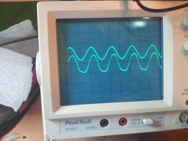
today i tried to calibrate the device but i got in calibration process 1 and 2
2 waveforms with same amplitude but they DONT are 90degrees different in phase.
any idea ?
i tested:
U8, pin 7: triangle. yes was a triangle
U9, pin 7: triangle - yes yes is a triangle
U9, pin 1: square wave - yes |
Failure gone.
I never tried before both channels together in my Oscilloscope,
Trigger Setting wrong.
Further i Must change R51 to 330ohm.
51k like described here is to much.
Original Layout Shows 430ohm.
The Jumper Setting near u10 must close to the right side.
Must say its a very |
|
|
Back to top
|
|
|
The Bad Producer

Joined: Mar 08, 2009
Posts: 282
Location: The Manhole
|
| Posted: Fri Sep 06, 2013 2:10 am Post subject:
|
|
|
Hey LED-man, just saw this, glad you got it sorted, but now I'm wondering what you were going to say?!
| Quote: | | Must say its a very... |
_________________
http://loudestwarning.tumblr.com/ |
|
|
Back to top
|
|
|
LED-man
Joined: Feb 22, 2013
Posts: 40
Location: Germany
|
| Posted: Fri Sep 06, 2013 2:51 am Post subject:
|
|
|
| The Bad Producer wrote: | Hey LED-man, just saw this, glad you got it sorted, but now I'm wondering what you were going to say?!
| Quote: | | Must say its a very... |
|
Very good attention here.
Would say, its a fantastic device.
I post here a video later.
Have to solder few jacks and finish the separate psu connection. |
|
|
Back to top
|
|
|
roglok

Joined: Aug 28, 2010
Posts: 202
Location: uptown
|
| Posted: Fri Sep 06, 2013 9:02 am Post subject:
|
|
|
| LED-man wrote: | | The Bad Producer wrote: | Hey LED-man, just saw this, glad you got it sorted, but now I'm wondering what you were going to say?!
| Quote: | | Must say its a very... |
|
Very good attention here.
Would say, its a fantastic device.
I post here a video later.
Have to solder few jacks and finish the separate psu connection. |
aww. i'm so jealous. would love to build one myself, but alas - no PCB for sale anywhere... |
|
|
Back to top
|
|
|
LED-man
Joined: Feb 22, 2013
Posts: 40
Location: Germany
|
| Posted: Fri Sep 06, 2013 9:27 am Post subject:
|
|
|
| roglok wrote: | | LED-man wrote: | | The Bad Producer wrote: | Hey LED-man, just saw this, glad you got it sorted, but now I'm wondering what you were going to say?!
| Quote: | | Must say its a very... |
|
Very good attention here.
Would say, its a fantastic device.
I post here a video later.
Have to solder few jacks and finish the separate psu connection. |
aww. i'm so jealous. would love to build one myself, but alas - no PCB for sale anywhere... |
I have tried to contact miss haible, but i'm unable to find a telephone number or valid email adress.
User harryw has contacted me last year, never heard again.
Im frustrated because he told me juergen leave 2000 pcbs !
WE must produce our own pcbs.
We need planning here. |
|
|
Back to top
|
|
|
elmegil

Joined: Mar 20, 2012
Posts: 2179
Location: Chicago
Audio files: 16
|
| Posted: Fri Sep 06, 2013 11:59 am Post subject:
|
|
|
The PCB situation as I understand it is that the estate is a mess, because there was paperwork unfinished when Juergen died, and it is unclear whether his estate goes in any part to his wife (they were in process of divorcing) or all to his children. The German authorities have not put any evident effort into resolving this and so it is still far up in the air.
Many people do not wish to make PCBs even though they are capable, because they want Juergen's stock, which are hard assets of his estate, to retain its value, and if everyone can get someone else's PCB of the same design then what reason is it for the originals to have much value (aside from collectors)? The point being that value should benefit his heirs, and everyone wants that to be the case.
Knobhell proposed a middle way -- go ahead and produce some new PCBs with the understanding that a donation from each would go to a fund for Juergen's children or heirs++ -- and was roundly shot down.
I don't think most would object to people producing PCBs for their own personal use, but I expect any attempt to sell them, even just to help cover base costs, would raise a lot of negative attention.
++ Note this is my paraphrase of what he proposed, so if it is not accurate in any way, that is on me. But the discussion of these things is in the public forums here and on Muffwiggler, so you can verify my account. |
|
|
Back to top
|
|
|
LED-man
Joined: Feb 22, 2013
Posts: 40
Location: Germany
|
| Posted: Fri Sep 06, 2013 12:21 pm Post subject:
|
|
|
Has anybody here contacted Birgit haible in Last 12months ?
I think no !
I cant find informations here and in German Forums.
WE are the DIY Community and potentiell customers.
So lets start here, either we get contact and a clear Situation from Birgit or we start a own Production.(with % to Birgits Kids)
I think its in Jürgens interest to deploy/produce the Part of his genial livework.
its Same like Bob Moog, Paul S and other Great Technican.
His work need recognition here and yet.. Not only in history
Http://www.DSL-man.de. - Share your DIY Projects |
|
|
Back to top
|
|
|
KnobHell
Joined: Jan 28, 2012
Posts: 56
Location: SLC
|
| Posted: Sun Sep 29, 2013 7:20 am Post subject:
|
|
|
Not the freqeency shifter, but positive movement none the less. I predicted this would happen and got pissed on pretty heavily.
Living vco project.
http://www.muffwiggler.com/forum/topic-93892.html
The market always takes care of itself. I'd expect to see more designs come out well before the German government settles his estate. |
|
|
Back to top
|
|
|
LED-man
Joined: Feb 22, 2013
Posts: 40
Location: Germany
|
|
|
Back to top
|
|
|
gwpt
Joined: Feb 24, 2012
Posts: 3
Location: Australia
|
|
|
Back to top
|
|
|
LED-man
Joined: Feb 22, 2013
Posts: 40
Location: Germany
|
|
|
Back to top
|
|
|
|

 Forum index » DIY Hardware and Software » Jürgen Haible designs