| Author |
Message |
Ruebezahl

Joined: Mar 09, 2014
Posts: 112
Location: Taiwan
Audio files: 4
|
 Posted: Sun Oct 05, 2014 3:28 am Post subject: Posted: Sun Oct 05, 2014 3:28 am Post subject:
|
  |
|
Since nobody had an answer, i went on, experimenting myself  Well in another thread somebody suggested to use zenerdiodes for lowering the voltage. i read on those and even did some maths to find out what Resistorvalue i have to place in front.(min. 90R) I startet with 100 but the Trigger-LED, would again, just glow a little bit, and the sound is just a little click. I changed the resistor values and also exchanged the zdiode, but nothing changed. Actually i even tried to trigger it from 15V directly, the click was a little louder but still not really a kick. I really dont know whats wrong? Well in another thread somebody suggested to use zenerdiodes for lowering the voltage. i read on those and even did some maths to find out what Resistorvalue i have to place in front.(min. 90R) I startet with 100 but the Trigger-LED, would again, just glow a little bit, and the sound is just a little click. I changed the resistor values and also exchanged the zdiode, but nothing changed. Actually i even tried to trigger it from 15V directly, the click was a little louder but still not really a kick. I really dont know whats wrong?
Is the Method with a Z-Diode maybe not sufficient aswell? Should i use a Voltage Regulator? But i am pretty sure by now that there is at least another error in the Drum-Circuit argh Unfortunately i cant measure the voltages right now, because i destroyed my multimeter recently.
Multimeter: I wanted to measure the consumption of the bass drum in Ampere, but unfortunately i was measuring from + to - pole, while the power was on, so my multimeter is broken now. Now i know that you should never do that  But apart from the multimeter, is it likely that some parts in the circuit took damage? But apart from the multimeter, is it likely that some parts in the circuit took damage?
Thanks for your help, although my questions are very vague and its more like a brainstorming with myself...
_________________
https://soundcloud.com/ruebezahl |
|
|
Back to top
|
|
 |
blue hell
Site Admin

Joined: Apr 03, 2004
Posts: 24678
Location: The Netherlands, Enschede
Audio files: 330
G2 patch files: 320
|
| Posted: Sun Oct 05, 2014 4:07 am Post subject:
|
|
|
Depends on the power supply if its broken now or not, when it uses regulator ICs it is probably fine.
For the stuff after the power supply, that most likely is still OK, it just saw the power supply go down.
The meter may just have blown a fuse? Maybe internal, check it's manual to find out.
_________________
Jan
also .. could someone please turn down the thermostat a bit.

9 3 4 .. erm .. not 13 then? .. hmm, ah eight! .. yeah yeah as in 8647 .. 47 is an 88 .. pwew .. numbles! |
|
|
Back to top
|
|
|
Ruebezahl
Joined: Mar 09, 2014
Posts: 112
Location: Taiwan
Audio files: 4
|
| Posted: Sun Oct 12, 2014 5:59 am Post subject:
|
|
|
Hey BlueHell, you were right, about the Multimeter. After replacing the fuse, its working again...
I made some progress, but its still not working right. First, the Trigger-Signal is working right now, with a stable 12V high. Thats for the good news.
Still no proper sound though. I did some measuring, and the problem seems to be right at the beginning of the circuit. after C1, at Pin 3 of the IC, the voltage suddenly drops from the 12V-triggersignal to a lousy 3,4V. on pin2, the other input of the amp, its exactly the same value. whenever there is a trigger, those values go up like 0,01V lol. On the Output (Pin1) however, i measure -13,59V, wich is going up to -13,53. So it seems the voltage is really low suddenly after C1. Maybe this has to be that way, i dont know. but what is really weird, that after the first op-amp stage, the voltage is negative. Is this opamp inverting the signal?
For the sound. its more a click than a kick. The potentiometers all shape the sound though, in a way. so its not like there is no sound at all. its just much less voluminous than it should be, and super super quiet. have to turn my volume up a lot to really hear it.
Maybe someone can point me in the right direction? i dont really know what could be wrong. checked the part values already, there doesnt seem to be an error.
_________________
https://soundcloud.com/ruebezahl |
|
|
Back to top
|
|
|
Ruebezahl
Joined: Mar 09, 2014
Posts: 112
Location: Taiwan
Audio files: 4
|
| Posted: Wed Oct 29, 2014 6:56 pm Post subject:
|
|
|
Sorry for bumping, but does really nobody have an idea on that? Especially the question if the first op-amp stage is meant to invert the signal?
I also noted that neither of the LEDs are blinking (The Trigger LED did before), though they are not broken.
_________________
https://soundcloud.com/ruebezahl |
|
|
Back to top
|
|
|
jbeuckm

Joined: Nov 30, 2008
Posts: 165
Location: Stockholm
Audio files: 9
|
| Posted: Fri Nov 07, 2014 9:20 am Post subject:
|
|
|
The drum sounds really nice to me with interesting tweaking options. There are definitely settings where the sound is down to a click or stops altogether, so keep tweaking until the bass 
Note: I'm on +/-12V supply with a TL072 and +5V gate signal coming from an arduino. I have not done much with the limiter connected yet, but it's a totally different sound with one LED connected there.
I made a layout with the power lines into a Eurorack connector and generated the g-code to etch this on a router (.2mm 60degree etching bit). I also did a front panel in Cambam but I haven't tried that yet.
https://github.com/jbeuckm/hip_bass_drum |
|
|
Back to top
|
|
|
Ruebezahl
Joined: Mar 09, 2014
Posts: 112
Location: Taiwan
Audio files: 4
|
| Posted: Fri Nov 07, 2014 11:25 am Post subject:
|
|
|
Hmm, na, i am sure, its not me turning the wrong knobs  i attached a file how my kick sounds. i mean it would be okay, if in some positions the kick would sound like this. but i turned all the knobs, and its still jsut like this. Just no PHAT Kick Sound, how it should be. i attached a file how my kick sounds. i mean it would be okay, if in some positions the kick would sound like this. but i turned all the knobs, and its still jsut like this. Just no PHAT Kick Sound, how it should be.
I tried trigger it from different voltages 5-12. i actually didnt try powering it from 12, but it actually should work from 15V and i dont think thats the problem. Also none of the LEDs is glowing right now, althugh they are not broken... i dont know, i am pretty hopeless by now :S
| Description: |
| its there, but... not really :S |
|

Download (listen) |
| Filename: |
nottherightkick.mp3 |
| Filesize: |
3.9 MB |
| Downloaded: |
1526 Time(s) |
_________________
https://soundcloud.com/ruebezahl |
|
|
Back to top
|
|
|
wackelpeter
Joined: May 05, 2013
Posts: 461
Location: germany
Audio files: 10
|
|
|
Back to top
|
|
|
Ruebezahl
Joined: Mar 09, 2014
Posts: 112
Location: Taiwan
Audio files: 4
|
| Posted: Thu Nov 13, 2014 9:30 pm Post subject:
|
|
|
Aww man, i might just try the Strip-Board one. I actually wanted my first self-etched board see to work, but i really need an "Erfolgserlebnis" now.
Yes an Oscilloscope is on my Wishlist, but didn't check for one yet.
For the Pots. Yes actually. There IS change when i turn them, and actually they do exactly what they should do. Just the overall Sound is just lame and no KICK more a CLICK. But i can chance the clicks resonance, thud, decay and so on. Maybe the problem is somewhere at the decay? I dont know. I gotta sleep now, but thanks for the Input
_________________
https://soundcloud.com/ruebezahl |
|
|
Back to top
|
|
|
wackelpeter
Joined: May 05, 2013
Posts: 461
Location: germany
Audio files: 10
|
| Posted: Sat Nov 15, 2014 2:48 am Post subject:
|
|
|
maybe you should post du a pic of your board and layout... maybe there is a mistake and you didn't noticed that yet...
speaking for myself, whenever i have a module not running i check the board twice or more before i ask for help, but sometimes i've looked 10 times over my board and didn't noticed a simple brdige i forgot or swapped Inputs on Ic's... well i mean sometimes it's hard to see the wood because of the trees...
_________________
https://soundcloud.com/bastian-j |
|
|
Back to top
|
|
|
Ruebezahl
Joined: Mar 09, 2014
Posts: 112
Location: Taiwan
Audio files: 4
|
| Posted: Sun Nov 16, 2014 10:56 pm Post subject:
|
|
|
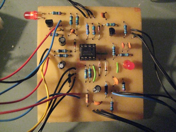
Okay i made some Pictures. In Place of the 6 LED for Limiting there is just one. Shouldn't be a problem, though. You can have a look at it, and maybe you will find something. Hopefully! Thanks!
Layout from KRS1972, earlier in this thread:


| Description: |
| The whole Setup with Power Supply and Trigger Circuit |
|
| Filesize: |
2.16 MB |
| Viewed: |
1008 Time(s) |
| This image has been reduced to fit the page. Click on it to enlarge. |

|
| Description: |
|
| Filesize: |
625.52 KB |
| Viewed: |
981 Time(s) |
| This image has been reduced to fit the page. Click on it to enlarge. |
|
| Description: |
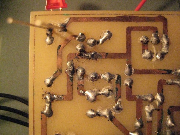
| The Board from the Back. Sometimes it looks like there are unwanted bridges, but its just some kind of dirt, not solder... |
|
| Filesize: |
625.58 KB |
| Viewed: |
897 Time(s) |
| This image has been reduced to fit the page. Click on it to enlarge. |

|
| Description: |
| Close Up. The green stuff is dirt from the soldering tin. I don't know, is this normal? I think its the dried flux?! |
|
| Filesize: |
374.17 KB |
| Viewed: |
891 Time(s) |
| This image has been reduced to fit the page. Click on it to enlarge. |
|
_________________
https://soundcloud.com/ruebezahl |
|
|
Back to top
|
|
|
wackelpeter
Joined: May 05, 2013
Posts: 461
Location: germany
Audio files: 10
|
| Posted: Mon Nov 17, 2014 8:24 am Post subject:
|
|
|
ouch... the solder Points doesn't look so good... is this lead free solder you're using? a year back or so i accidentally bought lead free solder too... it's terrible stuff... you should better use solder with lead as it's much better to solder and cold solder Points are better visible... those on your pcb look nearly all like cold solder Points to me... could be the solder, the one i had looked similar...
also you should clean the pcb Scratching that dirt off of it and then go other it with a Piece of Cloth...
especially those dirty points between traces and next to other solder Points as you can't see if there's a small Bridge underneath them...
i do use a very small skrew driver and an old tooth brush and a magnifier...
p.s. youre shure on your 4558 chip that there isn't a Bridge at pin 1 and 2? Looks a lot like that...
the limiter led isn't that important and can also be omitted together with that Switch... it's just really loud w/o led's...
btw. i'm thinking that someone could also Switch that led's electrical in and out to get some Kknd of Accent like the dr-606 had it...
_________________
https://soundcloud.com/bastian-j |
|
|
Back to top
|
|
|
Ruebezahl
Joined: Mar 09, 2014
Posts: 112
Location: Taiwan
Audio files: 4
|
| Posted: Mon Nov 17, 2014 9:37 pm Post subject:
|
|
|
Hey, the Solder is indeed strange. first there are is this weird green dirt everywhere. they emerge out of the liquid around the solder spots. i guess its the "flussmittel". but normally it shouldnt become a green, dry mass later. Also its sparking sometimes while soldering. not really sparks in terms of light, but more sparks in the accoustic sense. it goes "brrz" when i solder.
But its not lead-free. In fact it ahs a lot of lead. Its S-Pb60Sn40. I dont know what the S means, but it has 60% Lead and 40% tin. A quick research got me the information that normally it should be the other way round. This might really be the problem.
I think i gonna get myself a decent solder and do it all again. And FUCK CONRAD, they told me there is no difference i should just buy whatever i want, so of course i got the cheaper one...
edit: actually i found another thread where they say its complettely okay  http://www.rc-network.de/forum/showthread.php/326314-Pb60Sn40-anstatt-Sn60Pb40-L%C3%B6tzinn-auch-ok (german) http://www.rc-network.de/forum/showthread.php/326314-Pb60Sn40-anstatt-Sn60Pb40-L%C3%B6tzinn-auch-ok (german)
but i jsut cleaned it a little with a toothbrush (good tip) and try it again
_________________
https://soundcloud.com/ruebezahl |
|
|
Back to top
|
|
|
Ruebezahl
Joined: Mar 09, 2014
Posts: 112
Location: Taiwan
Audio files: 4
|
| Posted: Tue Nov 18, 2014 1:19 am Post subject:
|
|
|
ITS WORKING! Well at least it did
I changed the Trigger-LED because it was not working anymore. After that, the bassdrum actually sounded like a bass drum. I was heavily distorting my soundcard input though, so just a few settings sounded good. so i lowered the resistor value of R16 (just like wackelpeter suggested) However, now the Trigger-LED is broken again, and its super distortet everything haha I need to go to Uni now but, i change the LED again. maybe the resistor in front of it, is broken too? i gonna see tonight.
But thanks for your help so far, i am a lot closer to my goal now
_________________
https://soundcloud.com/ruebezahl |
|
|
Back to top
|
|
|
tokyomatik

Joined: Jan 20, 2011
Posts: 171
Location: berlin
Audio files: 6
|
| Posted: Fri Aug 07, 2015 3:16 am Post subject:
|
|
|
I finished to build one and worked directly....I can confirm that thge layout is working
is a simple but powerful and interesting bass drum...I already love it |
|
|
Back to top
|
|
|
ElAndreas
Joined: Sep 22, 2015
Posts: 3
Location: Sweden
|
| Posted: Tue Sep 22, 2015 12:32 pm Post subject:
Resistor at -12V input burns |
|
|
I have used the strip board layout posted here. I use a PC psu with +/-12V. When I connect the -12V to the board the resistor R2(R23 in the original layout) burns after a few seconds. I use 1/4W Metal Film resistors. For the pots I use 20k instead of 10k because they were available. Other than that I use the parts as stated in the layout.
I am new to electronics and would appreciate it if someone could give me advice on how to troubleshoot the circuit. |
|
|
Back to top
|
|
|
elmegil

Joined: Mar 20, 2012
Posts: 2179
Location: Chicago
Audio files: 16
|
| Posted: Tue Sep 22, 2015 1:15 pm Post subject:
|
|
|
You have a short somewhere. Use a meter with the power off to measure resistance (or use the continuity tester function if you have it) between -12V and ground and -12V and +12V. You very likely will see zero (or nearly so) ohms or hear the beep that means there's continuity. Then trace the tracks for those voltages around the PCB and ensure there are no solder shorts. Then, assuming you've socketed your chips, pull the chips and see if you still have a short. If not, then you have a bad chip; put them back in one at a time and measure after each one to figure out which it is.
Also, if you etched the board yourself, examine it with a magnifying glass to make sure there aren't any residual copper traces causing this. |
|
|
Back to top
|
|
|
ElAndreas
Joined: Sep 22, 2015
Posts: 3
Location: Sweden
|
| Posted: Mon Sep 28, 2015 2:13 am Post subject:
|
|
|
| elmegil wrote: | You have a short somewhere. Use a meter with the power off to measure resistance (or use the continuity tester function if you have it) between -12V and ground and -12V and +12V. You very likely will see zero (or nearly so) ohms or hear the beep that means there's continuity. Then trace the tracks for those voltages around the PCB and ensure there are no solder shorts. Then, assuming you've socketed your chips, pull the chips and see if you still have a short. If not, then you have a bad chip; put them back in one at a time and measure after each one to figure out which it is.
Also, if you etched the board yourself, examine it with a magnifying glass to make sure there aren't any residual copper traces causing this. |
Thanks a lot for your informative reply!
I went over the board and cleaned it up and found that I had mounted C2 (C10 in the schema) in the wrong direction. After replacing it the resistor does not burn but I do not get any sound. The trigger led D2 (D5 in the schema) glows constantly, with a faint light, even when no trigger voltage is applied. I this the correct operation of the led? Is it possible that other components were damaged? |
|
|
Back to top
|
|
|
ElAndreas
Joined: Sep 22, 2015
Posts: 3
Location: Sweden
|
| Posted: Thu Oct 01, 2015 2:21 am Post subject:
|
|
|
| Is the trigger LED supposed to glow constantly or only when a trigger signal is received? |
|
|
Back to top
|
|
|
elmegil
Joined: Mar 20, 2012
Posts: 2179
Location: Chicago
Audio files: 16
|
| Posted: Thu Oct 01, 2015 5:41 am Post subject:
|
|
|
| Only when a trigger is received. |
|
|
Back to top
|
|
|
wackelpeter
Joined: May 05, 2013
Posts: 461
Location: germany
Audio files: 10
|
| Posted: Fri Oct 02, 2015 9:59 am Post subject:
|
|
|
Depends also on the Position of the PW-Pot... in my own built at least...
when turned fully in one direction widest PW it's permanently on without any Trigger applied to the Input...
As i see you used a stripboard... is the pot correctly wired? don't have the schematics right here... are the outer wipers going to the right power rails... maybe -15V instead of gnd? or something like this...
ok checked the schematics... seems like your suspect area is around the Inputs of IC1A... all resistors going to the right places, correct values? would check this again...
_________________
https://soundcloud.com/bastian-j |
|
|
Back to top
|
|
|
lysergist
Joined: Jan 14, 2016
Posts: 36
Location: France
Audio files: 2
|
| Posted: Fri Jan 15, 2016 4:54 pm Post subject:
|
|
|
Be careful if you make the stripboard version, 2N3904 are upside down. They need to be inverted, Emitter goes to GND. Pot wiring is inverted too.
Cheers it sounds really awesome for a little circuit. |
|
|
Back to top
|
|
|
jeanpat
Joined: Jan 15, 2018
Posts: 7
Location: france
|
| Posted: Tue Apr 03, 2018 7:37 am Post subject:
|
|
|
Hi guys!
Noob question, but whitout it I could not learn.
Could the hip bass drum work under +/-9v without any adaptation, and will it sound the same?
Thank's. |
|
|
Back to top
|
|
|
|

 Forum index » DIY Hardware and Software » The layout factory
