| Author |
Message |
-minus-
Joined: Oct 26, 2008
Posts: 787
Audio files: 13
|
 Posted: Thu Oct 25, 2012 6:02 am Post subject:
BUCHLA 111 Ring Modulator Stripboard Posted: Thu Oct 25, 2012 6:02 am Post subject:
BUCHLA 111 Ring Modulator Stripboard
Subject description: Stripboard your own 100 Series |
  |
|
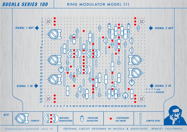
I stripboarded the 100 Series Buchla Ring Modulator from the discussion and schematics found in this thread:
http://electro-music.com/forum/topic-35574-25.html&sid=404eafa91e830ceed29f68c0cd61a18b
During construction I went on an extreme Buchla tangent and haven't been the same since.  I have been astounded by the brilliant design and elegant typography found on the Buchla panels. Just look at those fonts! I cannot honestly think of anything which comes visually close to this, synth or otherwise. This stuff is seriously in a league of it's own, as are the modules themselves. I have been astounded by the brilliant design and elegant typography found on the Buchla panels. Just look at those fonts! I cannot honestly think of anything which comes visually close to this, synth or otherwise. This stuff is seriously in a league of it's own, as are the modules themselves.
So here is the diagram... I have built this and it works. It seems to run on 12V fine, but on 15V as labelled in the original schematic, it will give you goose bumps! This is a nice circuit indeed. I spent an hour trying to figure out the trimming. Without data on how to do this, I ended up playing around until it sounded good (to my ears). It's not the dual version as the original was, but it would be easy to make another. I tried to put the matched transistors as close together as possible. You can glue them together if you are concerned about temperature and stability. MFOS has information on this here:
http://www.musicfromouterspace.com/analogsynth_new/TRANSISTORMATCHER/TRANSISTORMATCHER.html
I used 2N3904 and 2N3906 throughout. You definitely should socket the transistors for this one. I matched mine on a breadboard using this simple circuit:
http://electro-music.com/forum/post-276867.html
It's the Yusynth one... 3rd post down.
I used 6.8uF tantalum caps as I couldn't get the 5.6uF ones. Also, you could use a ferrite bead in place of the 2.2 Ohm resistor at the power input. The board has been laid out to accommodate a variety of trimpots: Horizontal (as illustrated), Vertical, Piher Style, 25 Turn Cermet etc.
I shall post a sound clip or two in the coming days. Happy Buchla building!
| Description: |
| V2: Added missing rail No. 27 |
|
| Filesize: |
1.94 MB |
| Viewed: |
925 Time(s) |
| This image has been reduced to fit the page. Click on it to enlarge. |
|
Last edited by -minus- on Thu Oct 25, 2012 3:22 pm; edited 1 time in total |
|
|
Back to top
|
|
 |
elmegil

Joined: Mar 20, 2012
Posts: 2179
Location: Chicago
Audio files: 16
|
| Posted: Thu Oct 25, 2012 10:20 am Post subject:
|
|
|
Nice 
How important is it to have Tantalums as opposed to other high quality film-type caps? I don't know that I have any that big anyway, but figured I'd ask since I have avoided Tantalum as much as possible after hearing stories about magic smoke even if you look at them cross eyed |
|
|
Back to top
|
|
|
-minus-
Joined: Oct 26, 2008
Posts: 787
Audio files: 13
|
| Posted: Thu Oct 25, 2012 2:12 pm Post subject:
|
|
|
Good question, but I don't know the answer. I have read they can self-destruct but in the couple of times I have used them I've never had a problem. Perhaps you could just substitute electrolytic capacitors, say 4.7uF. There is enough room to extend the two 220 Ohm resistors up a rail and have room for caps across three hole. I was short two trimmers and had to steal from my breadboard. I'll hook up some rotaries there and do some experiments with different capacitors.
I'm thinking I might do more of these Buchla 100 series circuits. I'll change this topic title accordingly when this happens. |
|
|
Back to top
|
|
|
elmegil
Joined: Mar 20, 2012
Posts: 2179
Location: Chicago
Audio files: 16
|
| Posted: Thu Oct 25, 2012 4:50 pm Post subject:
|
|
|
The short form of the best story I heard was that a guy built a lab circuit for his EE class with tantalums, hooked them up backwards, and realized his mistake when the first one blew up. He quickly turned things off, turned the others around, and tested it and everything seemed fine.
Later, the others all exploded, even though they were hooked up correctly. That one time being backwards did enough damage that they weren't safe. |
|
|
Back to top
|
|
|
-minus-
Joined: Oct 26, 2008
Posts: 787
Audio files: 13
|
| Posted: Thu Oct 25, 2012 5:39 pm Post subject:
|
|
|

Thanks for the info. I'll be sure to keep my tantalum caps well away from the sack of KNO3 I have stored under my bed. |
|
|
Back to top
|
|
|
Snaper
Joined: Feb 28, 2014
Posts: 217
Location: Hungary
|
| Posted: Thu Jun 19, 2014 4:23 am Post subject:
|
|
|
| Could this run from 12V? |
|
|
Back to top
|
|
|
-minus-
Joined: Oct 26, 2008
Posts: 787
Audio files: 13
|
| Posted: Fri Jun 20, 2014 2:52 am Post subject:
|
|
|
| Mine runs on 12V and sounds pretty good. |
|
|
Back to top
|
|
|
Snaper
Joined: Feb 28, 2014
Posts: 217
Location: Hungary
|
| Posted: Fri Jun 20, 2014 5:19 am Post subject:
|
|
|
| -minus- wrote: | | Mine runs on 12V and sounds pretty good. |
Thanks! |
|
|
Back to top
|
|
|
Snaper
Joined: Feb 28, 2014
Posts: 217
Location: Hungary
|
| Posted: Sat Jun 21, 2014 7:11 am Post subject:
|
|
|
| Last question : size of the trimmers? |
|
|
Back to top
|
|
|
-minus-
Joined: Oct 26, 2008
Posts: 787
Audio files: 13
|
| Posted: Sat Jun 21, 2014 7:51 am Post subject:
|
|
|
Trimpots... Don't you hate that. I can't believe I have forgotten to mention the values there. I'll have a look at my board right now....
OK. The one on the bottom right is 20K. All the others are 1K.
Sorry I neglected to label those. I shall have to fix that up on the illustration. |
|
|
Back to top
|
|
|
Snaper
Joined: Feb 28, 2014
Posts: 217
Location: Hungary
|
| Posted: Sat Jun 21, 2014 8:23 am Post subject:
|
|
|
| -minus- wrote: | Trimpots... Don't you hate that. I can't believe I have forgotten to mention the values there. I'll have a look at my board right now....
OK. The one on the bottom right is 20K. All the others are 1K.
Sorry I neglected to label those. I shall have to fix that up on the illustration. |
Nice!
Will order the parts. |
|
|
Back to top
|
|
|
-minus-
Joined: Oct 26, 2008
Posts: 787
Audio files: 13
|
|
|
Back to top
|
|
|
Snaper
Joined: Feb 28, 2014
Posts: 217
Location: Hungary
|
| Posted: Sat Jun 21, 2014 11:18 am Post subject:
|
|
|
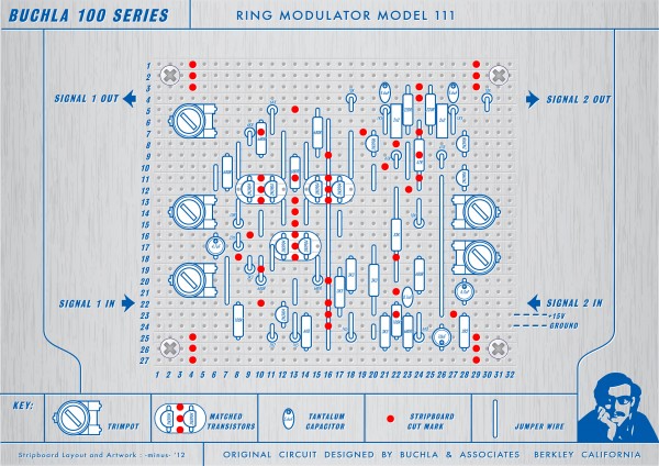
| -minus- wrote: | So here is the new version with correct trimpot values...
NOTE:
On the original Buchla schematic there is a missing value for one of the trimpots. On the first link I posted at the top of this page there is a pcb layout. I used a 20K the same as in that link above. |
Legend! |
|
|
Back to top
|
|
|
Snaper
Joined: Feb 28, 2014
Posts: 217
Location: Hungary
|
| Posted: Sun Jul 13, 2014 9:45 am Post subject:
|
|
|
Built it last day.
Not easy, and yes, it works from 12v, Im using it in my eurorack.
Sounds great, but you need to patch an amplifier after it, cause Buchla modules using line level (1.2 vpp). |
|
|
Back to top
|
|
|
lysergist
Joined: Jan 14, 2016
Posts: 36
Location: France
Audio files: 2
|
|
|
Back to top
|
|
|
lysergist
Joined: Jan 14, 2016
Posts: 36
Location: France
Audio files: 2
|
| Posted: Sat Sep 30, 2023 6:07 pm Post subject:
|
|
|
| By the way what's the point in having two outputs on opposite phase ? I'm not sure how could it be useful for a ring mod, am i missing something ? |
|
|
Back to top
|
|
|
|

 Forum index » DIY Hardware and Software