| Author |
Message |
Bodega
Joined: Nov 02, 2008
Posts: 75
Location: Montreal
|
 Posted: Thu Jun 11, 2009 4:02 pm Post subject:
Calculating Resistance for a passive 2-oct switcher? Posted: Thu Jun 11, 2009 4:02 pm Post subject:
Calculating Resistance for a passive 2-oct switcher?
Subject description: Anyone have any helpful leads? |
  |
|
Hi all,
I'm thinking of making a much, much simpler version of this dc voltage switch:
http://www.wiseguysynth.com/larry/jlh-822/822.htm
It would just be a single-channel input, an on-on-on switch and an output, if I can swing it.
So, position 1 would be input=output, 2 would be an octave down and 3 an octave below that. 2 and 3 would have resistors at a given value. And that's it.
It wouldn't be buffered... unless someone can convince me why it should be.
Does this sound like a feasible plan?
thanks lots!
Matthew |
|
|
Back to top
|
|
 |
andrewF

Joined: Dec 29, 2006
Posts: 1176
Location: australia
Audio files: 4
|
| Posted: Thu Jun 11, 2009 5:28 pm Post subject:
|
|
|
i think it would work with an op amp summer circuit, something like the CGS DC mixer.
just have your switch wired up to put out 0V, -1V, -2V, -3V, assuming you are planning 1V/oct
and have both your DC voltage and switch output as inputs to the opamp.....
is this something like you mean or am i totally off track  |
|
|
Back to top
|
|
|
Bodega
Joined: Nov 02, 2008
Posts: 75
Location: Montreal
|
| Posted: Thu Jun 11, 2009 9:35 pm Post subject:
|
|
|
You pretty much got it. It's for a MOTM-style system, so yes, I'd like a 0/-1v/-2v switch, or something along those lines.
| andrewF wrote: | | just have your switch wired up to put out 0V, -1V, -2V, -3V, assuming you are planning 1V/oct? |
That's what I was really wondering, is how to calculate the resistor values. A voltage divider is easy, but that's not exactly what I need. It seems I need a voltage subtractor. Does that make sense? I'm new to this, so maybe they're the same thing on some level.
I'm also unclear as to why a passive circuit wouldn't work, but maybe that's a whole other topic onto itself.... |
|
|
Back to top
|
|
|
andrewF
Joined: Dec 29, 2006
Posts: 1176
Location: australia
Audio files: 4
|
|
|
Back to top
|
|
|
Bodega
Joined: Nov 02, 2008
Posts: 75
Location: Montreal
|
| Posted: Fri Jun 12, 2009 6:44 am Post subject:
|
|
|
| andrewF wrote: | | With passive mixers the inputs affect each other, having an opamp 'isolates' each input. |
Interesting - that does actually clear things up a bit.
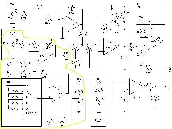
In that schem, all those resistors in the lower left are 1k? That would make things considerably easier.
I definitely want to keep it as simple as possible, so no tune pot. Why is the pot connected to +12v? Does that VCO require both +/-15 AND +12? |
|
|
Back to top
|
|
|
andrewF
Joined: Dec 29, 2006
Posts: 1176
Location: australia
Audio files: 4
|
| Posted: Fri Jun 12, 2009 7:37 am Post subject:
|
|
|
No I don't think it has to be 12V, probably just a typo.
I had a look around Motohiko's page a bit more,
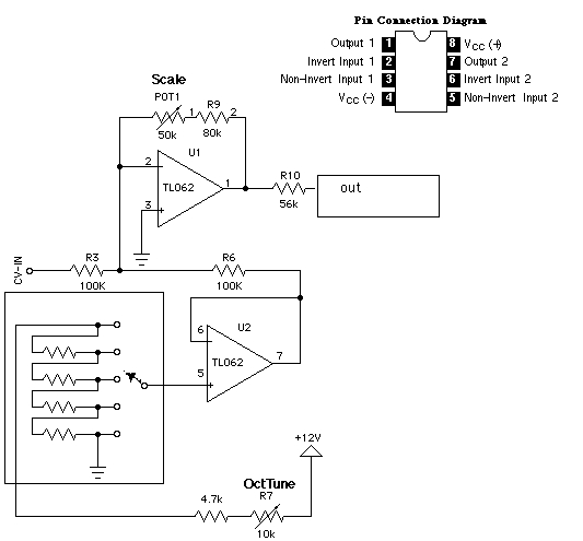
there is a simpler version of the circuit here
http://www.aleph.co.jp/~takeda/radio/img/farmVCOII-scheme.gif
a bit easier to make.
you could run this circuit with +/-15V or +/-12V.
for the opamps, TL072 or TL082 will do the job.
You could probably leave out the tune pot, but the scale and oct tune pots are essential. these can just be trimpots on the PCB, hopefully once you set this module it won't need to be adjusted.
The 1k resistors should be metal and matched (buy 20 and test them with a multimeter to find 4 of the same value).
i think you can see on the circuit, the oct tune pot and 4k7 resistor form a voltage divider circuit with the 1 k resistors. The opamp is set up as a voltage follower (and inverter if you change the connections as i described), it protects your voltage divider outputs from being affected by other parts of the circuit. |
|
|
Back to top
|
|
|
Bodega
Joined: Nov 02, 2008
Posts: 75
Location: Montreal
|
| Posted: Sun Jun 14, 2009 3:46 pm Post subject:
|
|
|
Thanks, Andrew!
Maybe I'll try and perfboard up one of those in the next few days and see how it goes. I'll leave out the tune pot and R2.
Am I right in thinking that I can take out R3/R4 if I only have one CV in? |
|
|
Back to top
|
|
|
andrewF
Joined: Dec 29, 2006
Posts: 1176
Location: australia
Audio files: 4
|
| Posted: Sun Jun 14, 2009 4:42 pm Post subject:
|
|
|
| Bodega wrote: |
Am I right in thinking that I can take out R3/R4 if I only have one CV in? |
You can leave out R3 OR R4, the CV in will have to pass thru 100k before it gets to the opamp.
have fun! |
|
|
Back to top
|
|
|
Bodega
Joined: Nov 02, 2008
Posts: 75
Location: Montreal
|
| Posted: Sun Jun 14, 2009 8:40 pm Post subject:
|
|
|
| Duly noted. Thanks again! |
|
|
Back to top
|
|
|
BananaPlug

Joined: Jul 04, 2007
Posts: 307
Location: Philly
Audio files: 5
|
| Posted: Fri Jun 19, 2009 7:37 am Post subject:
|
|
|
| For the matched resistors you might want to buy a resistor network. Digi-key 770-83-R1KP-ND for example. |
|
|
Back to top
|
|
|
Bodega
Joined: Nov 02, 2008
Posts: 75
Location: Montreal
|
| Posted: Fri Jun 19, 2009 10:58 am Post subject:
|
|
|
| That would make things easier. Nice one BananaPlug. |
|
|
Back to top
|
|
|
Bodega
Joined: Nov 02, 2008
Posts: 75
Location: Montreal
|
|
|
Back to top
|
|
|
Bodega
Joined: Nov 02, 2008
Posts: 75
Location: Montreal
|
| Posted: Sat Jun 27, 2009 7:14 pm Post subject:
|
|
|
Built it. It worked! Made up a little video. It's a bit dumbed-down for the general public.
http://www.youtube.com/watch?v=TkeUYXMFfrY
I ended up taking out the scale pot - I'd rather not mess with a master detune.
Nice little project for a Saturday afternoon. |
|
|
Back to top
|
|
|
lilpaula87
Joined: May 11, 2020
Posts: 12
Location: Italy
|
| Posted: Fri Nov 13, 2020 11:39 pm Post subject:
|
|
|
| Bodega wrote: | Built it. It worked! Made up a little video. It's a bit dumbed-down for the general public.
http://www.youtube.com/watch?v=TkeUYXMFfrY
I ended up taking out the scale pot - I'd rather not mess with a master detune.
Nice little project for a Saturday afternoon. |
Great job! I would like to create a module with a couple of octave switch for my VCOs. As I’m a real noob could you be so kind to share your strip board layout? 😊 |
|
|
Back to top
|
|
|
|

 Forum index » DIY Hardware and Software