| Author |
Message |
acidblue
Joined: Jun 26, 2009
Posts: 226
Location: The Darkside
|
|
|
Back to top
|
|
 |
Inventor
Stream Operator

Joined: Oct 13, 2007
Posts: 6221
Location: near Austin, Tx, USA
Audio files: 267
|
|
|
Back to top
|
|
|
acidblue
Joined: Jun 26, 2009
Posts: 226
Location: The Darkside
|
 Posted: Sat Sep 05, 2009 8:49 pm Post subject: Posted: Sat Sep 05, 2009 8:49 pm Post subject:
|
  |
|
Actually its 250mw, but damn! your right, I didn't even consider that.
I had no idea using 2.5w speaker would make the chip run hot.
So I'm off to find a another speaker, I Think Sparkfun has some.
BTW, what would be a good chip to use for 2.5w speakers? |
|
|
Back to top
|
|
|
Inventor
Stream Operator
Joined: Oct 13, 2007
Posts: 6221
Location: near Austin, Tx, USA
Audio files: 267
|
| Posted: Sat Sep 05, 2009 8:56 pm Post subject:
|
|
|
I don't know, I would cruise the www.national.com site for audio amplifiers. I do not know much about them, but surely you will need a heatsink of some sort due to the maximum power condition which states that at best the source must dissipate as much as the load. Maybe someone with more experience will chime in soon.
Les
_________________
"Let's make noise for peace." - Kijjaz |
|
|
Back to top
|
|
|
Thomas_Henry
Joined: Jul 24, 2009
Posts: 170
Location: N. Mankato, MN
Audio files: 3
|
| Posted: Sun Sep 06, 2009 1:17 am Post subject:
|
|
|
Hello,
| acidblue wrote: |
I had no idea using 2.5w speaker would make the chip run hot.
|
It doesn't. The power rating of your loudspeaker has nothing to do with this. The rating you mention (whether 2.5 watts or 250 milliwatts) simply indicates what the loudspeaker can handle before it breaks down. You could hook a 100 watt speaker up to it if you want (but it probably wouldn't work efficiently) and everything would run cool.
But back to your problem. It's been ages since I've done anything with the LM380/384/386 type chips, but I do remember always providing extra copper clad foil on the PCB to help dissipate heat. Try heat sinking the thing. Another possibility is supersonic parasitic oscillations. Check the various connections on your scope and see if you notice anything untoward.
Anyway, the wattage capability of your loudspeaker isn't an issue despite the previous comments. (Impedance is more important here, but I think you said you're using a 6 ohm one, which is pretty much in the ball park of what the chip can handle.)
Thomas Henry |
|
|
Back to top
|
|
|
Inventor
Stream Operator
Joined: Oct 13, 2007
Posts: 6221
Location: near Austin, Tx, USA
Audio files: 267
|
| Posted: Sun Sep 06, 2009 3:07 am Post subject:
|
|
|
I stand corrected. Thomas_Henry seems to know what he is talking about. I'd check those higher frequency oscillations, and look into the RC shunt in the datasheet, maybe that's what it's for?
Les
_________________
"Let's make noise for peace." - Kijjaz |
|
|
Back to top
|
|
|
RF

Joined: Mar 23, 2007
Posts: 1502
Location: Northern Minnesota, USA
Audio files: 28
|
|
|
Back to top
|
|
|
acidblue
Joined: Jun 26, 2009
Posts: 226
Location: The Darkside
|
| Posted: Sun Sep 06, 2009 12:22 pm Post subject:
|
|
|
Thanks Tom for clearing things up, yippie! I don't have to buy more speakers.
BTW I don't have a scope, it'a on my xmas list.
MMM. RF my schematic dosn't have the cap and resistor going to ground on pin 5.
I wonder if that's the reason im getting hot chips.
I'll adjust my breadboard circuit and give it a go.
I'll get back with the results.
Last edited by acidblue on Sun Sep 06, 2009 1:00 pm; edited 1 time in total |
|
|
Back to top
|
|
|
acidblue
Joined: Jun 26, 2009
Posts: 226
Location: The Darkside
|
| Posted: Sun Sep 06, 2009 12:48 pm Post subject:
|
|
|
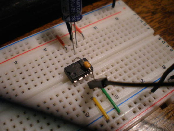
Ok I'm still getting a hot LM386 chip.
I've included pics of my breadboard circuit.
I didn't have a 10 ohm R nor a 0.05uF cap, so I used 330 R and a 0.1uF cap.
I don't think that will make too much a difference.
The larger chip is the 4093.
| Description: |
|
| Filesize: |
68.34 KB |
| Viewed: |
313 Time(s) |
| This image has been reduced to fit the page. Click on it to enlarge. |

|
| Description: |
|
| Filesize: |
58.42 KB |
| Viewed: |
303 Time(s) |
| This image has been reduced to fit the page. Click on it to enlarge. |

|
|
|
|
Back to top
|
|
|
Inventor
Stream Operator
Joined: Oct 13, 2007
Posts: 6221
Location: near Austin, Tx, USA
Audio files: 267
|
| Posted: Sun Sep 06, 2009 6:49 pm Post subject:
|
|
|
Cool man, detailed photos and stuff. I would imagine that your component values are not appropriate for the application. If it were me, I'd get the right parts, even if I had to go to Radio Shack for some quickie parts. Also you probably don't want little parts for this, especially the resistor. I'd get a 1/2 watt or bigger resistor if they have it. That's because your speaker is 6 ohms and you're using a 10 Ohm resistor sort of in parallel, so you don't want to toast a 1/4 Watt resistor.
Those are just my inexperienced thoughts, I'll let wiser folks more in the know critique them for you. Best of luck with it.
Les
_________________
"Let's make noise for peace." - Kijjaz |
|
|
Back to top
|
|
|
DGTom

Joined: Dec 08, 2008
Posts: 211
Location: Adelaide
Audio files: 3
G2 patch files: 1
|
| Posted: Sun Sep 06, 2009 6:52 pm Post subject:
|
|
|
| I might be wrong.. but to me it looks as tho the resistor on the right with the little cap won't actually be doing anything will it? |
|
|
Back to top
|
|
|
State Machine
Janitor


Joined: Apr 17, 2006
Posts: 2810
Location: New York
Audio files: 24
|
| Posted: Sun Sep 06, 2009 6:57 pm Post subject:
|
|
|
No doubt, the thing is oscillating way beyond audible levels as Thomas mentioned a few posts back. I would hang a 0.1 uF capacitor, AS CLOSE TO THE CHIP AS YOU CAN GET, from Vcc to ground. That will clean things up and it will most likely run cool as a cucumber. lol ........ would not hurt to also put a 10 uF bypass capacitor near the 0.1 uF also. 
Bill |
|
|
Back to top
|
|
|
Inventor
Stream Operator
Joined: Oct 13, 2007
Posts: 6221
Location: near Austin, Tx, USA
Audio files: 267
|
| Posted: Sun Sep 06, 2009 7:04 pm Post subject:
|
|
|
Duh, I didn't even think of that Bill, nice work. I suspect that the 10uF cap is going to be the thing that's really needed in this application and the 0.1uF only makes it better, but what do I know? Probably too much for my own good, lol.
Les
_________________
"Let's make noise for peace." - Kijjaz |
|
|
Back to top
|
|
|
acidblue
Joined: Jun 26, 2009
Posts: 226
Location: The Darkside
|
| Posted: Sun Sep 06, 2009 7:22 pm Post subject:
|
|
|
| State Machine wrote: | No doubt, the thing is oscillating way beyond audible levels as Thomas mentioned a few posts back. I would hang a 0.1 uF capacitor, AS CLOSE TO THE CHIP AS YOU CAN GET, from Vcc to ground. That will clean things up and it will most likely run cool as a cucumber. lol ........ would not hurt to also put a 10 uF bypass capacitor near the 0.1 uF also.
Bill |
Could you describe "hang"
Or better yet how about a schematic. |
|
|
Back to top
|
|
|
magman
Joined: Feb 04, 2009
Posts: 363
Location: Liverpool, UK
|
| Posted: Sun Sep 06, 2009 10:32 pm Post subject:
|
|
|
As DGTom stated (and looking at the large Cap as well), these components are actually being shorted out by the connections on the breadboard (the 5 connections in a row are shorted together - that's how these breadboards work).
You will need to make these connections in adjacent rows to give them separate connections.
For example, move the negative (short) leg of the electrolytic cap from from I49, to I50, also move the output connection from J49 to J50. Then move the long leg of the resistor from H52 to H51 and the capacitor from I52 to I51.
Try this first then lets see how the circuit behaves, but the decoupling cap already mentioned would then be a good addition.
I suspect the reason the chip is getting hot is that you have effectively put a low resistance to ground on the output (the speaker), because the output capacitor is being shorted. Here's hoping this hasn't cooked the chip.
Regards
Magman |
|
|
Back to top
|
|
|
aerogramma

Joined: Feb 27, 2008
Posts: 156
Location: Roma, Italy - London, UK
Audio files: 13
|
| Posted: Sun Sep 06, 2009 11:49 pm Post subject:
|
|
|
| magman wrote: | As DGTom stated (and looking at the large Cap as well), these components are actually being shorted out by the connections on the breadboard (the 5 connections in a row are shorted together - that's how these breadboards work).
You will need to make these connections in adjacent rows to give them separate connections.
For example, move the negative (short) leg of the electrolytic cap from from I49, to I50, also move the output connection from J49 to J50. Then move the long leg of the resistor from H52 to H51 and the capacitor from I52 to I51.
Try this first then lets see how the circuit behaves, but the decoupling cap already mentioned would then be a good addition.
I suspect the reason the chip is getting hot is that you have effectively put a low resistance to ground on the output (the speaker), because the output capacitor is being shorted. Here's hoping this hasn't cooked the chip.
Regards
Magman |
I think magman and DGtom are right ... the negative pin of the 220uf electrolytic cap should be connected as advised here
|
|
|
Back to top
|
|
|
Inventor
Stream Operator
Joined: Oct 13, 2007
Posts: 6221
Location: near Austin, Tx, USA
Audio files: 267
|
| Posted: Mon Sep 07, 2009 12:43 am Post subject:
|
|
|
Oh so if I get this right, you folks took a close look at the photos and figured out that there was a wiring error? I think I see it too, on pin 5 of the LM386, right? How cool is that? DIY help debugging by photograph now, nice! This could be a new angle on helping each other here on the forum. Your circuit don't work? Take a photo of it. Neat.
Les
_________________
"Let's make noise for peace." - Kijjaz |
|
|
Back to top
|
|
|
State Machine
Janitor
Joined: Apr 17, 2006
Posts: 2810
Location: New York
Audio files: 24
|
| Posted: Mon Sep 07, 2009 7:49 am Post subject:
|
|
|
Magman,
Great eyes there man !! Just to explain a bit further, even with no signal input, this amplifier centers it's output at 1/2 of Vcc. This means that if you have a 9V supply, the output will be sitting at 4.5V. The decoupling capacitor that is now shorted allows this to be applied to 8 ohms to ground. The amp is trying to deliver 2.5W to the speaker .. ouch . but it can't and thus gets HOT 
It's a good chance that the LM386 is destroyed so if you rearrange things and it still does not work, it's may just be a bad amplifier chip.
Les wrote:
| Quote: | | Duh, I didn't even think of that Bill, nice work. I suspect that the 10uF cap is going to be the thing that's really needed in this application and the 0.1uF only makes it better, but what do I know? Probably too much for my own good, lol. |
The 10uF capacitor is good at filtering things like low frequency ripple on the supply line but it's really not good at higher frequencies and acts like an inductor. This is why the 0.1 uF capacitor is there, to filter the high frequency stuff. The 0.1 uF is good at shunting any RF to ground around the chip. This is why you see them in pairs sometimes.
acid wrote:
| Quote: |
Could you describe "hang" |
My bad. That's a slang term to connecting an additional component to an existing circuit. Hang thus is synonymous with connect. I meant to say, connect a 0.1 uF between pins 6 and pin 4. No observation of polarity is necessary. Additionally, the 10 uF [+] lead would connect to pin 6 and it's [-] lead to pin 4.
Bill |
|
|
Back to top
|
|
|
fluxmonkey
Joined: Jun 24, 2005
Posts: 708
Location: cleve
|
|
|
Back to top
|
|
|
State Machine
Janitor
Joined: Apr 17, 2006
Posts: 2810
Location: New York
Audio files: 24
|
|
|
Back to top
|
|
|
acidblue
Joined: Jun 26, 2009
Posts: 226
Location: The Darkside
|
|
|
Back to top
|
|
|
State Machine
Janitor
Joined: Apr 17, 2006
Posts: 2810
Location: New York
Audio files: 24
|
| Posted: Mon Sep 07, 2009 5:00 pm Post subject:
|
|
|
Great news AND great collaboration by all I must say !! It's good to see the teamwork involved in helping others ...
Now it's time to amplify something
Bill
PS: Perfect capacitor hanging to ...  |
|
|
Back to top
|
|
|
acidblue
Joined: Jun 26, 2009
Posts: 226
Location: The Darkside
|
| Posted: Mon Sep 07, 2009 8:05 pm Post subject:
|
|
|
| State Machine wrote: | Great news AND great collaboration by all I must say !! It's good to see the teamwork involved in helping others ...
Now it's time to amplify something
Bill
PS: Perfect capacitor hanging to ... |
Yes, big thanks to every one.
Gonna amplify a 4093, got 2 gates connected already, gonna do 4 in a bit.
Didn't know i could hang so well.
Guess you could say my cap is well hung |
|
|
Back to top
|
|
|
|

 Forum index » DIY Hardware and Software