| Author |
Message |
mosc
Site Admin

Joined: Jan 31, 2003
Posts: 18249
Location: Durham, NC
Audio files: 226
G2 patch files: 60
|
 Posted: Tue Mar 30, 2010 1:03 pm Post subject:
Pulse wave demodulator Posted: Tue Mar 30, 2010 1:03 pm Post subject:
Pulse wave demodulator |
  |
|
On another topic, http://electro-music.com/forum/post-290079.html#290079 , the G2 guys are talking about using their synths to control external equipment. Believe it or not, there is no CV output from a G2. Some guys are modifying their machines to short out the decoupling caps on their output. This works, but one accident and poof, there goes your prized G2. 
I was thinking that a simpler method would be to build a simple Pulse Width Demodulator for the output. This would be external. A Pulse Width Modulator would be very simple to patch up in the G2, of course.
I don't build any more, as many of you know, so I'm planting the seed for a discussion here with the hope that some of you will take this idea and build upon it so that we can come up with a useful circuit.
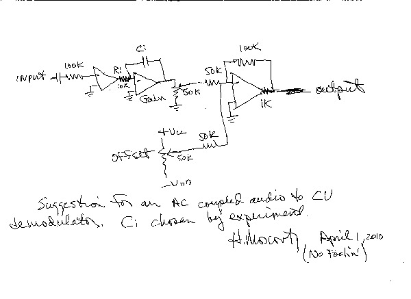
So, here's the ideal. A pulse width modulator is simply a square wave running at a constant frequency that is with a CV to adjust the pulse width. That's trivial to do in a G2. The demodulator is a circuit that converts the audio signal back to a CV, for controlling external gear like a Moog filter or whatever.
The basic circuit is just an OP amp integrator,

Anyway, if one selects the cap value correctly, then the output will follow the pulse width. I'd suggest using about a 10 KHz square wave in the G2 so the demodulator will run fast enough.
A second op amp circuit with inversion, offset, and scaling would make this thing more useful for the G2 users.
I think this isn't a bad thing for modular builders to have in their bag of tricks.
Please, those that are interest, take a look at this and see if you can flesh this idea out into something that will work. I think a lot of people would appreciate it.
_________________
--Howard
my music and other stuff |
|
|
Back to top
|
|
 |
fonik

Joined: Jun 07, 2006
Posts: 3950
Location: Germany
Audio files: 23
|
| Posted: Tue Mar 30, 2010 1:52 pm Post subject:
|
|
|
an integrator is a kind of lowpass, isn't it? anyways, i would think this is the common way to create CV from PWM. however the lowpass i.e. tom wiltshire uses is a little bit more complex...

http://www.electricdruid.net
_________________

cheers,
matthias
____________
Big Boss at fonitronik
Tech Buddy at Random*Source |
|
|
Back to top
|
|
|
blue hell
Site Admin

Joined: Apr 03, 2004
Posts: 24454
Location: The Netherlands, Enschede
Audio files: 297
G2 patch files: 320
|
| Posted: Tue Mar 30, 2010 2:00 pm Post subject:
|
|
|
Howards circuits has a lil problem, but I don't think it will be fixed by a circuit as posted by Matthias.
The problem is that that the circuit is coupled AC to the synth, so the average Vi will be zero, no matter what the pulse width is. So Vo will be zero as well.
I think an AM system should be used, i.e. an averaging rectifier instead of an integrator.
_________________
Jan
also .. could someone please turn down the thermostat a bit.
 |
|
|
Back to top
|
|
|
varice

Joined: Dec 29, 2004
Posts: 961
Location: Northeastern shore of Toledo Bend
Audio files: 29
G2 patch files: 54
|
| Posted: Tue Mar 30, 2010 3:11 pm Post subject:
|
|
|
| Blue Hell wrote: | Howards circuits has a lil problem, but I don't think it will be fixed by a circuit as posted by Matthias.
The problem is that that the circuit is coupled AC to the synth, so the average Vi will be zero, no matter what the pulse width is. So Vo will be zero as well.
I think an AM system should be used, i.e. an averaging rectifier instead of an integrator. |
http://electro-music.com/forum/post-290103.html#290103
| varice wrote: | Sorry, but you cannot derive a DC signal from an integrator that is getting an AC signal input! For that integrator idea to work, the input signal must already have an average DC offset!
If you are really scared of modifying the G2 for DC output, then amplitude modulate a square wave output and use a fast response envelope follower. That would work... kinda... |
_________________
varice |
|
|
Back to top
|
|
|
blue hell
Site Admin
Joined: Apr 03, 2004
Posts: 24454
Location: The Netherlands, Enschede
Audio files: 297
G2 patch files: 320
|
| Posted: Tue Mar 30, 2010 4:12 pm Post subject:
|
|
|

_________________
Jan
also .. could someone please turn down the thermostat a bit.
|
|
|
Back to top
|
|
|
frijitz
Joined: May 04, 2007
Posts: 1734
Location: NM USA
Audio files: 54
|
|
|
Back to top
|
|
|
varice
Joined: Dec 29, 2004
Posts: 961
Location: Northeastern shore of Toledo Bend
Audio files: 29
G2 patch files: 54
|
| Posted: Tue Mar 30, 2010 7:23 pm Post subject:
|
|
|
| frijitz wrote: | | You could use a standard FM transmission link? Like an FM tape recorder? |
What are you saying? Please explain...
Ummmm... in that thread it was suggested (as I already have) that a fall back solution to a DC output mod is to use an amplitude modulated output with an external envelope follower...
_________________
varice |
|
|
Back to top
|
|
|
frijitz
Joined: May 04, 2007
Posts: 1734
Location: NM USA
Audio files: 54
|
| Posted: Tue Mar 30, 2010 8:24 pm Post subject:
|
|
|
.
Last edited by frijitz on Thu Apr 01, 2010 8:20 am; edited 1 time in total |
|
|
Back to top
|
|
|
parasat

Joined: Aug 13, 2009
Posts: 33
Location: chicago
|
| Posted: Tue Mar 30, 2010 8:54 pm Post subject:
|
|
|
Why not use a LM1496N for the modem?
I assume the G2 can mimic a ring mod with one channel dc coupled.
Use the LM1496N to demodulate, then voila, your both right (kinda) 
-parasat
who now has visions of G2s running x-modem protocol and circular redundancy checks on the outboard DAC... |
|
|
Back to top
|
|
|
varice
Joined: Dec 29, 2004
Posts: 961
Location: Northeastern shore of Toledo Bend
Audio files: 29
G2 patch files: 54
|
| Posted: Wed Mar 31, 2010 1:19 am Post subject:
|
|
|
deleted stupid post
_________________
varice
Last edited by varice on Wed Mar 31, 2010 9:54 pm; edited 2 times in total |
|
|
Back to top
|
|
|
frijitz
Joined: May 04, 2007
Posts: 1734
Location: NM USA
Audio files: 54
|
| Posted: Wed Mar 31, 2010 1:52 am Post subject:
|
|
|
.
Last edited by frijitz on Thu Apr 01, 2010 8:21 am; edited 1 time in total |
|
|
Back to top
|
|
|
fonik
Joined: Jun 07, 2006
Posts: 3950
Location: Germany
Audio files: 23
|
| Posted: Wed Mar 31, 2010 1:54 am Post subject:
|
|
|
why not just blocking the negative excursions of the PWM signal on the input of the demodulator?
_________________
cheers,
matthias
____________
Big Boss at fonitronik
Tech Buddy at Random*Source |
|
|
Back to top
|
|
|
varice
Joined: Dec 29, 2004
Posts: 961
Location: Northeastern shore of Toledo Bend
Audio files: 29
G2 patch files: 54
|
| Posted: Wed Mar 31, 2010 3:00 am Post subject:
|
|
|
deleted stupid post
_________________
varice
Last edited by varice on Wed Mar 31, 2010 9:51 pm; edited 1 time in total |
|
|
Back to top
|
|
|
kkissinger
Stream Operator

Joined: Mar 28, 2006
Posts: 1438
Location: Kansas City, Mo USA
Audio files: 45
|
| Posted: Wed Mar 31, 2010 5:59 am Post subject:
Re: Pulse wave demodulator |
|
|
| mosc wrote: | On another topic, http://electro-music.com/forum/post-290079.html#290079 , the G2 guys are talking about using their synths to control external equipment. Believe it or not, there is no CV output from a G2. Some guys are modifying their machines to short out the decoupling caps on their output. This works, but one accident and poof, there goes your prized G2.
I was thinking that a simpler method would be to build a simple Pulse Width Demodulator for the output. This would be external. A Pulse Width Modulator would be very simple to patch up in the G2, of course... |
Mosc's circuit would track frequency changes -- you wouldn't necessarily have to control it with the duty-cycle.
If you use FM instead of PWM, then you don't have to worry about DC coupling issues. Would that work?
_________________
-- Kevin
http://kevinkissinger.com |
|
|
Back to top
|
|
|
frijitz
Joined: May 04, 2007
Posts: 1734
Location: NM USA
Audio files: 54
|
| Posted: Wed Mar 31, 2010 7:28 am Post subject:
|
|
|
| fonik wrote: | | why not just blocking the negative excursions of the PWM signal on the input of the demodulator? |
Yes, of course. Two ways to do this: (a) a half-wave rectifier using a diode to clip the negative excursion, (b) put the signal through a comparator referenced to ground. I think Howard's scheme is probably the simplest method to use for this problem. But I would probably use FM demodulated by a LM331 F/V converter.

Ian |
|
|
Back to top
|
|
|
slacker
Joined: Nov 18, 2007
Posts: 301
Location: England
Audio files: 11
G2 patch files: 1
|
| Posted: Wed Mar 31, 2010 10:58 am Post subject:
|
|
|
Sorry if this is a stupid idea, but couldn't you just basically use an envelope follower type circuit?
Feed it an audio signal that changes in volume, and you'll get a DC CV out of it. |
|
|
Back to top
|
|
|
varice
Joined: Dec 29, 2004
Posts: 961
Location: Northeastern shore of Toledo Bend
Audio files: 29
G2 patch files: 54
|
| Posted: Wed Mar 31, 2010 11:10 am Post subject:
|
|
|
| slacker wrote: | Sorry if this is a stupid idea, but couldn't you just basically use an envelope follower type circuit?
Feed it an audio signal that changes in volume, and you'll get a DC CV out of it. |
No, an envelope follower is not a stupid idea  And it has already been suggested. And it has already been suggested.
| varice wrote: | | Blue Hell wrote: | Howards circuits has a lil problem, but I don't think it will be fixed by a circuit as posted by Matthias.
The problem is that that the circuit is coupled AC to the synth, so the average Vi will be zero, no matter what the pulse width is. So Vo will be zero as well.
I think an AM system should be used, i.e. an averaging rectifier instead of an integrator. |
http://electro-music.com/forum/post-290103.html#290103
| varice wrote: | Sorry, but you cannot derive a DC signal from an integrator that is getting an AC signal input! For that integrator idea to work, the input signal must already have an average DC offset!
If you are really scared of modifying the G2 for DC output, then amplitude modulate a square wave output and use a fast response envelope follower. That would work... kinda... |
|
_________________
varice
Last edited by varice on Wed Mar 31, 2010 11:33 am; edited 2 times in total |
|
|
Back to top
|
|
|
slacker
Joined: Nov 18, 2007
Posts: 301
Location: England
Audio files: 11
G2 patch files: 1
|
| Posted: Wed Mar 31, 2010 11:14 am Post subject:
|
|
|
Oops I missed that  |
|
|
Back to top
|
|
|
fonik
Joined: Jun 07, 2006
Posts: 3950
Location: Germany
Audio files: 23
|
| Posted: Wed Mar 31, 2010 11:18 am Post subject:
|
|
|
what about the G2 side? would one prefer PWM or FM? does it matter at all?
_________________
cheers,
matthias
____________
Big Boss at fonitronik
Tech Buddy at Random*Source |
|
|
Back to top
|
|
|
kkissinger
Stream Operator
Joined: Mar 28, 2006
Posts: 1438
Location: Kansas City, Mo USA
Audio files: 45
|
| Posted: Wed Mar 31, 2010 11:29 am Post subject:
|
|
|
| Blue Hell wrote: | | The problem is that that the circuit is coupled AC to the synth, so the average Vi will be zero, no matter what the pulse width is. So Vo will be zero as well. |
You could place a Schmitt trigger prior to the integrator. Then, the average Voltage will vary with the frequency and/or the pulse width.
Incidentally, this is the technique that the Paia Theremax uses to convert the Theremin's pitch to a control voltage output that tracks pitch.
http://paia.com/ProdArticles/theresch.htm
Check out purple-highlighted section at the lower left.
_________________
-- Kevin
http://kevinkissinger.com |
|
|
Back to top
|
|
|
varice
Joined: Dec 29, 2004
Posts: 961
Location: Northeastern shore of Toledo Bend
Audio files: 29
G2 patch files: 54
|
| Posted: Wed Mar 31, 2010 10:00 pm Post subject:
|
|
|
I would like to apologize to Howard, Ian, and parasat for my harsh tone and criticism about this topic. It was totally unnecessary. I will go back and clean up my posts.
_________________
varice |
|
|
Back to top
|
|
|
mosc
Site Admin
Joined: Jan 31, 2003
Posts: 18249
Location: Durham, NC
Audio files: 226
G2 patch files: 60
|
| Posted: Wed Mar 31, 2010 11:48 pm Post subject:
|
|
|
| kkissinger wrote: | | Blue Hell wrote: | | The problem is that that the circuit is coupled AC to the synth, so the average Vi will be zero, no matter what the pulse width is. So Vo will be zero as well. |
You could place a Schmitt trigger prior to the integrator. Then, the average Voltage will vary with the frequency and/or the pulse width.
|
Sure, any kind of comparator could convert the AC coupled output from the G2 into a nice solid rectangular wave. The effect of that AC coupling cap is neutralized by a zero crossing detector. Good suggestion.
FM demodulation as suggested would work, of course, but PWM is much simpler. IMHO. Most FM demodulators work over a relatively narrow frequency range. They usually detect a time varying signal, not necessarily a constant, but that's not to say it can't be done.
The AM modulation scheme that was suggested will work too, but it is hard to calibrate the G2 output. This is because there are so many ways the amplitude of the G2 can be changed both in the patch and in the G2 system. My experience in playing the G2 almost exclusively in live performance teaches me this. The PWM doesn't need calibration because the level of the output is not critical.
A quad op amp and a few passive components would do the trick. Input comparator - integrator - invert, scale and offset. One free op amp.
With a little more design you could superimpose a gate or AM on the PWM output to generate a gate or even a second CV output. This adds more complications on both ends.
There is more that can be done, but just getting a single CV with PWM shouldn't be that difficult.
Thanks for the comments. Good ones.
_________________
--Howard
my music and other stuff |
|
|
Back to top
|
|
|
mosc
Site Admin
Joined: Jan 31, 2003
Posts: 18249
Location: Durham, NC
Audio files: 226
G2 patch files: 60
|
|
|
Back to top
|
|
|
kkissinger
Stream Operator
Joined: Mar 28, 2006
Posts: 1438
Location: Kansas City, Mo USA
Audio files: 45
|
| Posted: Thu Apr 01, 2010 1:36 pm Post subject:
|
|
|
Ah, time to get out the breadboard!
You may need to apply some negative bias at the junction of the 100K resistor and the - input to the comparator. This will prevent unwanted firing of the comparator at narrow or 0% duty cycles.
An alternative to negative bias would be to apply positive bias to the + input -- that is, you would reference the comparator to an above-zero value rather than to ground.
I've been working lately with op amp based Schmitt triggers and comparators -- they can get fussy when the input voltage is at or near zero.
_________________
-- Kevin
http://kevinkissinger.com |
|
|
Back to top
|
|
|
varice
Joined: Dec 29, 2004
Posts: 961
Location: Northeastern shore of Toledo Bend
Audio files: 29
G2 patch files: 54
|
| Posted: Thu Apr 01, 2010 3:01 pm Post subject:
|
|
|
| mosc wrote: | | The AM modulation scheme that was suggested will work too, but it is hard to calibrate the G2 output. This is because there are so many ways the amplitude of the G2 can be changed both in the patch and in the G2 system. My experience in playing the G2 almost exclusively in live performance teaches me this. The PWM doesn't need calibration because the level of the output is not critical. |
In cases like mine though, where I’m also sending raw audio from the G2 to the moogerfooger filter, the G2 Patch Level and Master Level undesirably affect that level as well. So, one would still need to keep these levels fixed. The relative input level immunity of the PWM/integrator would not be of any benefit. The AM/envelope follower scheme is a more simple solution (as an alternative to a DC output mod). I simply leave the G2 Patch Level and Master Level set to max (which is a good thing to do anyway in the digital domain) and control the final patch output level with a mixer module within the patch. The master level is set by outboard mixer/monitor volume controls.
In my opinion, the best idea is to get a DC CV signal output (just like other modular synth CV output signals) for external control. The various AC to DC convertor schemes are overly complicated and full of unnecessary compromises. None of them can derive a DC output that has the same speed and integrity as the original DC signal. If there are concerns about protecting the DC output circuit, then the effort should be directed to just adding some protection instead of trying to come up with an AC to DC convertor compromise. Some protection ideas are discussed in my thread, including adding a current limiting/short circuit protection resistor in series with the DC output (as I did), adding a couple of overvoltage clamping diodes (as suggested by Jan), and adding a DC buffer opamp that could also double as a level amplifier/scaler.
_________________
varice |
|
|
Back to top
|
|
|
|

 Forum index » DIY Hardware and Software