| Author |
Message |
MC1495
Joined: Mar 24, 2009
Posts: 19
Location: baltimore
|
|
|
Back to top
|
|
 |
Tim Servo

Joined: Jul 16, 2006
Posts: 924
Location: Silicon Valley
Audio files: 11
|
 Posted: Fri Aug 05, 2011 4:41 pm Post subject:
Simple Window Comparator Posted: Fri Aug 05, 2011 4:41 pm Post subject:
Simple Window Comparator |
  |
|
Hey MC,
Not a detailed analysis, but off the top of my head, I'd say the feedback resistors on the first two op amps are way too small. To make an op amp act like a comparator, you need to eliminate the feedback R, or make it a very high value (5 to 10M). The feedback resistor gives snappier response (look up 'hysteresis'). Here's one example of an op amp based window comparator without the feedback resistors:
http://ecelab.com/circuit-window-comp.htm
If you really want the quickest response, then a comparator chip works better than an op amp. Here's a page with a pretty good rundown of comparator theory, and even includes a window comparator circuit:
http://home.cogeco.ca/~rpaisley4/Comparators.html
And finally, here's a really trick window comparator circuit that gives you voltage control over the window threshold and width. I suspect that a modern op amp like a TL07X would work just fine in place of the part numbers they call for. I haven't tried this one, but it certainly looks useful:
http://www.intersil.com/data/an/an9802.pdf
Tim (window comparator shopping) Servo |
|
|
Back to top
|
|
|
MC1495
Joined: Mar 24, 2009
Posts: 19
Location: baltimore
|
| Posted: Fri Aug 05, 2011 8:12 pm Post subject:
|
|
|
Tim - thank you for the advice, I did fail to take the hysteresis into serious consideration..
However, the 10meg resistors are not solving the problem.. the circuit only seems to be able to detect a very narrow window of voltage and even that is somewhat questionable... it mainly operates when the pots are turned all the way..
The other circuit does seem worth a shot, if there is not other possible explanation for my problems with this design. I know this is a pretty standard circuit, so my immediate suspicion would lead me to believe I made some sort of layout error - but I haven't been able to identify that yet...
I do wonder if there is some sort of issue with polarity here..many of the example circuits I've seen are single supply and this application note suggests using a pot that varies between V+ and ground, rather than V- for the max threshold... |
|
|
Back to top
|
|
|
StephenGiles
Joined: Apr 17, 2006
Posts: 507
Location: England
|
|
|
Back to top
|
|
|
Tim Servo
Joined: Jul 16, 2006
Posts: 924
Location: Silicon Valley
Audio files: 11
|
|
|
Back to top
|
|
|
frijitz
Joined: May 04, 2007
Posts: 1734
Location: NM USA
Audio files: 54
|
| Posted: Sat Aug 06, 2011 4:25 pm Post subject:
Re: Simple Window Comparator |
|
|
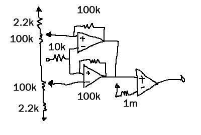
| MC1495 wrote: | | I've been trying out a window comparator circuit lately and have been having trouble for some reason. I thought I'd include the circuit here and see if people had some thoughts on why it might be problematic or share some other design insights. I don't think there is already a thread specifically dedicated to this circuit? |
I don't get what you are doing. You have the output opamp pinned at the negative rail. How can it ever switch? And why do you think you can connect the two opamp outputs together? It doesn't look like a standard circuit to me. Where did you get it?

Ian |
|
|
Back to top
|
|
|
MC1495
Joined: Mar 24, 2009
Posts: 19
Location: baltimore
|
|
|
Back to top
|
|
|
Tim Servo
Joined: Jul 16, 2006
Posts: 924
Location: Silicon Valley
Audio files: 11
|
| Posted: Sun Aug 07, 2011 1:59 pm Post subject:
Simple Window Comparator |
|
|
Hey MC,
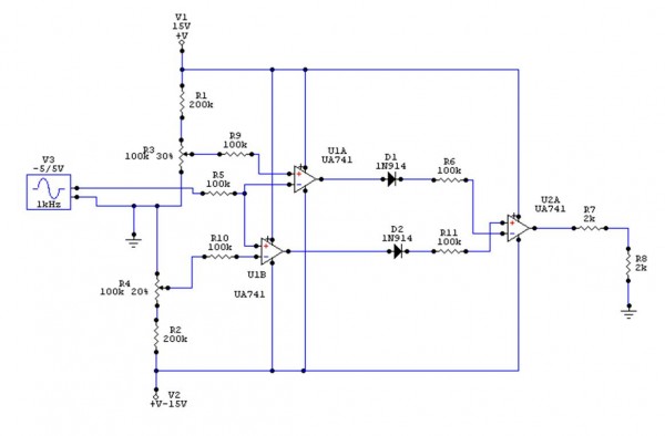
One quick note: the diodes in my circuit aren't needed. They'll actually cause the inputs on the last op-amp to float when reverse biased and so you can just remove them altogether. Thanks to Ian Fritz for the reminder.
I use an old version of Circuitmaker Student to simulate stuff, and the schemo is a screen shot (although it will also export circuits as WMF graphics). I'd love to find something that was as easy to use that worked under Windows 7, but it works great on my Win XP computer.
Tim (reverse biased) Servo |
|
|
Back to top
|
|
|
MC1495
Joined: Mar 24, 2009
Posts: 19
Location: baltimore
|
| Posted: Mon Aug 08, 2011 2:23 am Post subject:
|
|
|
Alright - I feel like I'm making a little progress here, although I might still be missing something... I apologize to protract this discussion on what seems to be a very elementary circuit..
Is the last stage supposed to operate as a differential amplifier circuit? It appears the same as the comparators, in which case I don't understand how the logic is working...
If it is a differential amplifier, this would be the operation:
If the voltage does not exceed the low threshold or the high threshold:
Low: -15v, High +15v.
(-15v minus 15v at differential amp)
If the voltage exceeds the low threshold, but not the high threshold:
Low: +15v, High: +15v.
(15v minus 15v at difference amp)
If the voltage exceeds the low threshold and the high threshold:
Low: +15v, High -15v.
(15v minus -15v at differential amp.)
So, one would get zero volts for the window and +15v or -15v for outside the window...is there a way to change this relationship so that there would be a +15v for the window and a -15v for things outside of the window? |
|
|
Back to top
|
|
|
Tim Servo
Joined: Jul 16, 2006
Posts: 924
Location: Silicon Valley
Audio files: 11
|
| Posted: Mon Aug 08, 2011 11:30 am Post subject:
Simple Window Comparator |
|
|
Hi MC,
I think you can change the output polarity by just swapping the inputs to the difference amp (R6 to + input, R11 to - input). Keep in mind I haven't actually built this, but a quick simulation seems to suggest that would do the trick.
Tim (just a simulation) Servo |
|
|
Back to top
|
|
|
MC1495
Joined: Mar 24, 2009
Posts: 19
Location: baltimore
|
| Posted: Thu Aug 11, 2011 8:45 am Post subject:
|
|
|
| Well, this does seem to be behaving rather nicely now...thanks for your help! |
|
|
Back to top
|
|
|
|

 Forum index » DIY Hardware and Software