| Author |
Message |
Uncle Krunkus
Moderator

Joined: Jul 11, 2005
Posts: 4761
Location: Sydney, Australia
Audio files: 52
G2 patch files: 1
|
 Posted: Sun Jul 05, 2009 7:16 pm Post subject: Posted: Sun Jul 05, 2009 7:16 pm Post subject:
|
  |
|
My concern isn't about safety, it's about having a definite ground to eliminate potential ground loop hum later on.
If this is the only PSU someone is using, there is no issue AFAIC. But as soon as you connect the modules hanging off this PSU to modules hanging off another PSU, you need the two PSUs ground connections connected at a star point. Or, if using interconnects which have a grounded shield (ie anything other than bananas) the ground would come through the shield, and that's okay I s'pose, as long as this PSU stays floating!  
Man! I'm starting to look at banana plugs in a whole different light. A system based on banana plugs has a lot less issues with potential ground loops hey?
_________________
What makes a space ours, is what we put there, and what we do there. |
|
|
Back to top
|
|
 |
RF

Joined: Mar 23, 2007
Posts: 1502
Location: Northern Minnesota, USA
Audio files: 28
|
| Posted: Sun Jul 05, 2009 9:16 pm Post subject:
|
|
|
It does make it quite a lot less expensive to use this design as opposed to buying a 36 V, or 24 volt or whatever center tap transformer. I used this design with a 12 V chasis mount transformer recently just to avoid having to buy one of those.
It also makes it pretty easy for someone not comfortable with any mains wiring to get off of batteries...
bruce
_________________
www.sdiy.org/rfeng
"I want to make these sounds that go wooo-wooo-ah-woo-woo.”
(Herb Deutsch to Bob Moog ~1963) |
|
|
Back to top
|
|
|
magman
Joined: Feb 04, 2009
Posts: 363
Location: Liverpool, UK
|
| Posted: Sun Jul 05, 2009 10:30 pm Post subject:
|
|
|
Folks,
Lets be careful not to make too big an issue of this and scare the newbies.
There are loads of electro-music devices out there that are effectively not grounded, just look at all of the keyboards and effects that have walwart PSU's and a 2 way connector from the walwart.
It is my understanding, that the key safety issue here of providing a power protective earth is if there are any exposed metal parts which are connected to the PSU ground of mains powered equipment. This is to prevent electric shocks from people touching the metal case in the circumstances of an electrical fault on the mains side (effectively connecting the mains to the metal case). If the mains never enters the case this is not an issue.
If you do have the mains powered PSU within the case, as with a mains transformer or a Power One PSU within the case for example, then there must be an electrical bond from all exposed metallic parts back to earth. I'm in the process of building an MFOS style modular case at the moment and all rack rails, panels and PSU will be connected to a common earthing point which is then connected to the mains earth.
Just my thoughts on this matter.
Regards
Magman |
|
|
Back to top
|
|
|
jacobian
Joined: Oct 14, 2008
Posts: 10
Location: san fran
|
| Posted: Thu Jul 09, 2009 8:23 pm Post subject:
|
|
|
@uncle...
I have a small portable system that will be using this psu. My plan was to use this system as a standalone to interface with other modules being powered by a separate power supply (travel rack and studio rack). If all of the modules are eurorack modules with shielded cables will this be a problem? Or am i strolling down a road of trouble?
Further, say I were to use these modules in tandem with modules that use banana's without ground. Will that be troublesome?
My plan was to use three of these power supplies to power all three systems (2 +/12 diy eurorack and one +/-15 diy cgs/buchla.
Thanks! |
|
|
Back to top
|
|
|
comrade_zero
Joined: Mar 05, 2009
Posts: 66
Location: arizona
Audio files: 4
|
| Posted: Tue Oct 06, 2009 11:47 pm Post subject:
|
|
|
I just wanted to say "thanks" to Ray for making this circuit available and to thundarr for the great layout. I just finished a nine volt version and it seems to be working great.
thanks for taking the time to do this, and especially for sharing it with us.
c_z |
|
|
Back to top
|
|
|
Skrog Productions

Joined: Jan 07, 2009
Posts: 1220
Location: Scottish Borders
Audio files: 159
|
| Posted: Wed Oct 07, 2009 2:38 pm Post subject:
|
|
|
Hi Thundarr, Magman is entirely right, don't worry too much till you start dealing with chassis/torroidal transformers, as an electrician i would insist on correct & adequet earthing arrangments when the project involves building your own 230V step down to 12v and/or 15v bi-polar supply. when you get to that stage i'll help you out if your stuck.
cheers
Dave |
|
|
Back to top
|
|
|
thundarr
Joined: Jun 07, 2009
Posts: 124
Location: Newcastle upon Tyne
|
|
|
Back to top
|
|
|
Skrog Productions
Joined: Jan 07, 2009
Posts: 1220
Location: Scottish Borders
Audio files: 159
|
| Posted: Thu Oct 08, 2009 10:47 am Post subject:
|
|
|
Hey that's cool dave, but when you get to the stage of violent module expansion quantity's ( 8 synth modules rising to 15 then 20...40.......172.....1000... etc) you'll def need a decent custom home made supply  , it will happen, sooner than you think, then it's time to buy that 5 bedroom house to keep it all in ( dreaming again) . , it will happen, sooner than you think, then it's time to buy that 5 bedroom house to keep it all in ( dreaming again) .
Tho i am interested in Uncle Krunkus's theoretical multiple half wave ground problems... maybe we could have a sticky thread for the mystical subject of earthing techniques and problems such as audio ground loops, i'd love a debate / solutions thread, anyone else agree ???
Seems the more you build the more you want to iron out the supply & hum problems of a large system.
 |
|
|
Back to top
|
|
|
Paradigm X
Joined: Feb 15, 2011
Posts: 363
Location: Null and void
Audio files: 2
|
| Posted: Wed Sep 21, 2011 8:17 am Post subject:
|
|
|
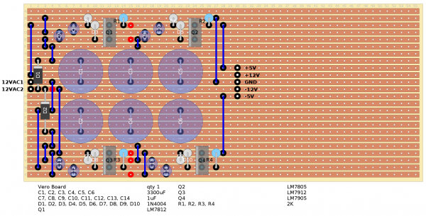
| thundarr wrote: | All built and tested with 1k loads, giving me +11.97V between + and ground and -11.94V between - and ground. That's close enough for me!
Re-arranged some components to allow more room for the 7812 and 7912 to lie flat and tidy some things up. The finished schematic is attached if anyone would find it useful.
Many thanks again for the help |
And thanks to you thundarr! (if youre still around)
Ive just built this and it works - getting +/-12v ! Ive had to solder the wall wart direct to the board because i forgot to buy a socket, but oh well.
I havent tested it 'with 1k loads' with, how do you do that please 
I appreciate this is an old thead but please anyone, feel free to chip in.
Cheers! |
|
|
Back to top
|
|
|
slacker
Joined: Nov 18, 2007
Posts: 301
Location: England
Audio files: 11
G2 patch files: 1
|
| Posted: Thu Sep 22, 2011 10:19 am Post subject:
|
|
|
| Paradigm X wrote: |
I havent tested it 'with 1k loads' with, how do you do that please
|
Temporarily connect a 1k resistor between +12 and ground and another between -12 and ground. This gives the power supply a load of about 12ma simulating a circuit being connected to it, if you now measure the voltages, you should still get roughly +-12 volts, which shows the regulators are working properly. |
|
|
Back to top
|
|
|
Paradigm X
Joined: Feb 15, 2011
Posts: 363
Location: Null and void
Audio files: 2
|
| Posted: Tue Oct 04, 2011 5:45 am Post subject:
|
|
|
Cool thanks man.
Obvious really
I was thinking of adding the indication LEDs in ken stone's version . That would do the same thing I beleive.
Thanks, Ben |
|
|
Back to top
|
|
|
dylar
Joined: Apr 25, 2011
Posts: 55
Location: iowa
|
| Posted: Tue Oct 11, 2011 8:54 pm Post subject:
hot regulator |
|
|
| I just built this according to the design in this thread. I think it is working, but one of the regulators gets very hot--I mean too hot to touch. I haven't hooked it up to anything yet...my multimeter is broken. One more question: in the semi-circles that represent the regulators in the layout does the flat side of the circle represent the metal side or the front side? I was reading it as one would a transistor where the rounded part represents the front. |
|
|
Back to top
|
|
|
dylar
Joined: Apr 25, 2011
Posts: 55
Location: iowa
|
| Posted: Wed Oct 12, 2011 7:48 pm Post subject:
|
|
|
| nevermind...figured it out. The flat side of the symbol is the metal side of the regulator (for those of you for whom this is confusing...which may just be me...don't know why it looked weird). |
|
|
Back to top
|
|
|
Paradigm X
Joined: Feb 15, 2011
Posts: 363
Location: Null and void
Audio files: 2
|
| Posted: Thu Oct 13, 2011 3:07 am Post subject:
|
|
|
Mine got pretty hot too... can just touhc but uncomfortable, rather than painful.
I put little heatshrinks on them, like these

but have since enclosed it all... hoping it will be alright. Maybe add a few holes for ventilation.
It also looks like i put them on the wrong way round 
Glad you figured the other thing out |
|
|
Back to top
|
|
|
carlhudson83
Joined: Nov 29, 2012
Posts: 8
Location: London
|
| Posted: Thu Nov 29, 2012 3:36 pm Post subject:
|
|
|
Hi everyone..
I've been trying to build the stripboard version of this circuit but I'm coming up against a brickwall..
I'm getting the +12V fine from the 7812.. But when I probe the out of the 7912 I get nothing.. I've tried a different regulator but still nothing - is it something to do with where the ground is?
I'm placing the black multimeter lead on the common ground line, and the ground pin of the 7812 - but can't find a voltage for it..
I read that a load resistor is required between the output and ground - I added a 3k resistor.. Still no voltage can be found..
Has anyone else had this problem? |
|
|
Back to top
|
|
|
olledahlberg
Joined: Nov 28, 2012
Posts: 23
Location: sweden
|
| Posted: Sat May 04, 2013 12:10 pm Post subject:
problem |
|
|
Ive made a 12, 0, -12 stripboard according to the layout. Ive made copper heat sinks and attached one for each regulator.
Instead of 1uF tantal caps, I have put 2.2uF el.lyt caps (will that work?)
My problem:
The regulators feels very hot already after some seconds, and the heat sinks gets hot as well (so at least they work).
I measure ca 14-15 V DC between 12 and ground.
I measure ca -0.6 V DC between the -12 and ground.
If I switch the multimeter to AC and measure the outputs (which should give no AC) I get like 30 V AC.
Im using a 12 V AC wall wart (gives about 13-13-0 when I measure with multimeter)
Im also using 2.4 K resistors between output and multimeter.
Iv tried to look over the board to see if I can see any obvious errors without finding any.
Cheers |
|
|
Back to top
|
|
|
olledahlberg
Joined: Nov 28, 2012
Posts: 23
Location: sweden
|
| Posted: Sat May 04, 2013 3:58 pm Post subject:
|
|
|
Problem solved, I think. When putting boh the regulators in the oppasite way, I get it to work fine. I must have totally got the layout wrong concerning those regulators. Now I get 11.84 and -12.01 V.
Only one thing I did not get. when I turn my multimeter to AC and measure the outputs it still show a lot of AC, roughly 24 V AC between positive out and ground and 51 V AC between pos and neg. This continue even when I pull ot the wall wart... |
|
|
Back to top
|
|
|
blue hell
Site Admin

Joined: Apr 03, 2004
Posts: 24498
Location: The Netherlands, Enschede
Audio files: 298
G2 patch files: 320
|
| Posted: Sat May 04, 2013 4:08 pm Post subject:
|
|
|
Looks like the multimeter has no AC coupling then but measures RMS instead?
edit: strike "instead" please as in instead
_________________
Jan
also .. could someone please turn down the thermostat a bit.
 |
|
|
Back to top
|
|
|
olledahlberg
Joined: Nov 28, 2012
Posts: 23
Location: sweden
|
| Posted: Sat May 04, 2013 4:24 pm Post subject:
|
|
|
| Yes, I guess... I think Ill trust the DC readings and I will use it for my almost finished MFOS Ultimate |
|
|
Back to top
|
|
|
blue hell
Site Admin
Joined: Apr 03, 2004
Posts: 24498
Location: The Netherlands, Enschede
Audio files: 298
G2 patch files: 320
|
| Posted: Sat May 04, 2013 4:48 pm Post subject:
|
|
|
| olledahlberg wrote: | | almost finished MFOS Ultimate |

good luck on the build!
_________________
Jan
also .. could someone please turn down the thermostat a bit.
|
|
|
Back to top
|
|
|
dadinfinitum
Joined: Dec 16, 2019
Posts: 41
Location: Maryland, US
|
|
|
Back to top
|
|
|
AlanP
Joined: Mar 11, 2014
Posts: 746
Location: New Zealand
Audio files: 41
|
| Posted: Thu Jul 15, 2021 8:01 am Post subject:
|
|
|
| Do a quick dry-fit to see if there is room for heatsinks on the regulators -- without heatsinks, I found on my first rack that the voltage rails sagged under load, and the regulators got way too hot. |
|
|
Back to top
|
|
|
dadinfinitum
Joined: Dec 16, 2019
Posts: 41
Location: Maryland, US
|
| Posted: Thu Jul 15, 2021 3:50 pm Post subject:
|
|
|
| AlanP wrote: | | Do a quick dry-fit to see if there is room for heatsinks on the regulators -- without heatsinks, I found on my first rack that the voltage rails sagged under load, and the regulators got way too hot. |
Yeah, I'll scoot some components around as needed to fit some on. Thanks! |
|
|
Back to top
|
|
|
PERFORMANCE
Joined: Jun 11, 2020
Posts: 36
Location: Germany
|
| Posted: Sun Aug 01, 2021 12:30 pm Post subject:
|
|
|
| Just a short question: Why -5V? |
|
|
Back to top
|
|
|
|

 Forum index » DIY Hardware and Software » MusicFromOuterSpace.com designs by Ray Wilson