| Author |
Message |
nicolas3141
Joined: May 25, 2007
Posts: 185
Location: Christchurch, New Zealand
|
|
|
Back to top
|
|
 |
nicolas3141
Joined: May 25, 2007
Posts: 185
Location: Christchurch, New Zealand
|
 Posted: Tue Jun 02, 2009 2:41 am Post subject: Posted: Tue Jun 02, 2009 2:41 am Post subject:
|
  |
|
Cripes that post makes me sound old. But then I feel old since turning forty the other day  |
|
|
Back to top
|
|
|
nicolas3141
Joined: May 25, 2007
Posts: 185
Location: Christchurch, New Zealand
|
| Posted: Tue Jun 02, 2009 2:45 am Post subject:
|
|
|
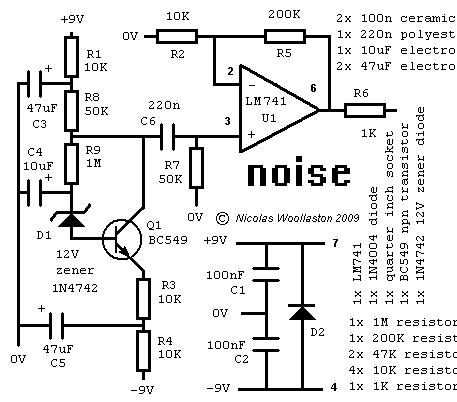
Oh and yes it should run fine on +/-12 or +/-15V. On higher voltage supplies you could try a higher voltage zener, say 15V. You would probably also want to boost the output a bit by replacing R2 with a cap and smaller resistor as described above.
Cheers,
Nicolas |
|
|
Back to top
|
|
|
Pehr

Joined: Aug 14, 2005
Posts: 1307
Location: Björkvik, Sweden
Audio files: 2
|
|
|
Back to top
|
|
|
oculus
Joined: Oct 30, 2011
Posts: 35
Location: Iceland, Reykjavik
|
| Posted: Tue Nov 15, 2011 5:40 pm Post subject:
|
|
|
hi Nicolas. thanks once again for a great project.
i just tried breadboard this it seems to work but it did sound a little weird to me at first to much low end and a little weak but then i moved my hand and blocked the light going on the breadboard and it sounded a little better
so i tried turning of the lights and then it sounded about right.
it seems to me that the light is affecting the diode. is this normal?
i just ordered the diode you listed so i should have the same as you listed.
here is a sample of this behavior
(you might have to do right click and save link as)
http://dl.dropbox.com/u/4440248/drasl/Noise%20light%20problem.mp3
later i tried changing battery´s and it sounded little more constant but still. here is a sample of that
http://dl.dropbox.com/u/4440248/drasl/Noise%20light%20problem.mp3
thanks kind regards
Fridfinnur |
|
|
Back to top
|
|
|
oculus
Joined: Oct 30, 2011
Posts: 35
Location: Iceland, Reykjavik
|
| Posted: Tue Nov 15, 2011 5:42 pm Post subject:
|
|
|
i forgot to mention i don´t know if this matters but i have R2 2.2k for more output and R5 220k as i didn´t have 200k
thanks Fridfinnur |
|
|
Back to top
|
|
|
frijitz
Joined: May 04, 2007
Posts: 1734
Location: NM USA
Audio files: 54
|
| Posted: Tue Nov 15, 2011 6:23 pm Post subject:
|
|
|
Have you measured the spectrum of the output noise?

Ian |
|
|
Back to top
|
|
|
frijitz
Joined: May 04, 2007
Posts: 1734
Location: NM USA
Audio files: 54
|
| Posted: Tue Nov 15, 2011 7:35 pm Post subject:
|
|
|
OK, I just had a real quick look at the posted files. In the dark, the spectrum is nice and flat over the mid-audio range with -6dB rolloffs at 30Hz and 16kHz.
The high-frequency rolloff seems due to the limited GBW of the 741 opamp. GBW = 1*10^6, Gain = 100 ==> BW = 10kHz. A faster opamp should give you a bit more "air" at the top end.
In the light, any diode will operate as a photodetector. The spectrum has strong peaks at 100, 200 and 300Hz ... obviously line frequency pickup via the room lights. The 100Hz component is very strong, in agreement with what you hear.
Anyway, it's a nice little circuit. Simple and effective.
Ian |
|
|
Back to top
|
|
|
oculus
Joined: Oct 30, 2011
Posts: 35
Location: Iceland, Reykjavik
|
| Posted: Wed Nov 16, 2011 1:10 am Post subject:
|
|
|
Nice thank you. I didn´t know about the light affecting diodes.
i just finished the noise on vero board. I changed a few things
i used tl72, i changed the c6 into 1uf ceramic, R2 - 2.2k, r5 - 220k,
and i switched the Bc549 into Bc547 it sounded to me a littlebit less agressive in the hi mid but it had something around 2 db less output.
kind regards Fridfinnur |
|
|
Back to top
|
|
|
elanhickler
Joined: Jun 24, 2008
Posts: 152
Location: Gilbert, Arizona
Audio files: 3
G2 patch files: 6
|
|
|
Back to top
|
|
|
elanhickler
Joined: Jun 24, 2008
Posts: 152
Location: Gilbert, Arizona
Audio files: 3
G2 patch files: 6
|
| Posted: Tue Oct 30, 2012 5:25 pm Post subject:
|
|
|
| How does one translate this circuit to a 15v PSU? |
|
|
Back to top
|
|
|
bubzy

Joined: Oct 27, 2010
Posts: 594
Location: United Kingdom
Audio files: 64
|
| Posted: Wed Oct 31, 2012 12:18 am Post subject:
Re: Noise source |
|
|
| nicolas3141 wrote: | Oh and yes it should run fine on +/-12 or +/-15V. On higher voltage supplies you could try a higher voltage zener, say 15V. You would probably also want to boost the output a bit by replacing R2 with a cap and smaller resistor as described.
|
| nicolas3141 wrote: | If you want to boost the output level, replace R2 with a capacitor (say 200-300n) and a smaller resistor (try 3-6K) in series (0V to cap, cap to R2, R2 to R5 and U1 as before).
|
so in summing up, for 15v operation, (thats +-15v) r2 is 3-6k and a new capacitor is introduced *Before* r2, at a value of about 200-300n
_________________
_Richard_  |
|
|
Back to top
|
|
|
elanhickler
Joined: Jun 24, 2008
Posts: 152
Location: Gilbert, Arizona
Audio files: 3
G2 patch files: 6
|
| Posted: Wed Oct 31, 2012 6:51 am Post subject:
|
|
|
 already anwered. not sure how I missed that, I've read this thread like 5 times. already anwered. not sure how I missed that, I've read this thread like 5 times. |
|
|
Back to top
|
|
|
|

 Forum index » DIY Hardware and Software