| Author |
Message |
egasimus

Joined: Feb 11, 2011
Posts: 113
Location: Bulgaria
|
 Posted: Fri Jan 06, 2012 9:31 am Post subject:
simple touch keyboards Posted: Fri Jan 06, 2012 9:31 am Post subject:
simple touch keyboards |
  |
|
Hey all,
I would like to etch myself a "keyboard" on a piece of copper clad. I prefer not to go the stylus route (although it's always an option) - so is there a reasonably simple to build circuit for a touch keyboard? I'm not afraid of AVR microcontrollers (don't have a programmer for PICs, though), but where's the fun in using one when we have CMOS 
Cheers,
Adam |
|
|
Back to top
|
|
 |
ericcoleridge

Joined: Jan 16, 2007
Posts: 889
Location: NYC
|
 Posted: Fri Jan 06, 2012 2:09 pm Post subject: Posted: Fri Jan 06, 2012 2:09 pm Post subject:
|
  |
|
short answer is no, there's no simple, easy touch keyboard.
If you do some research you can find some complicated difficult ones |
|
|
Back to top
|
|
 |
egasimus

Joined: Feb 11, 2011
Posts: 113
Location: Bulgaria
|
 Posted: Fri Jan 06, 2012 11:16 pm Post subject: Posted: Fri Jan 06, 2012 11:16 pm Post subject:
|
  |
|
how 'bout something based off this?

It's as simple as it gets - gotta experiment and see what it's good for. |
|
|
Back to top
|
|
 |
MadScientist
Joined: Nov 28, 2011
Posts: 63
Location: Denmark
|
 Posted: Sat Jan 07, 2012 4:42 am Post subject: Posted: Sat Jan 07, 2012 4:42 am Post subject:
|
  |
|
| egasimus wrote: | | how 'bout something based off this? |
If you are happy about having a 'grid' type of pattern for your fingers to make contacts across, then there is an even simpler way (though the schematic you show should work nicely as well).
Use a 40106 CMOS 6x Schmitt trigger inverter. Connect something like a 1-10Meg resistor from each input to either B+ or ground, depending on what polarity of the outputs you want. Then connect each inverter input to one side of your keyboard 'grid', while the other goes to the opposite of what you connected the resistor to. May also need a small capacitor across the keyboard grids to reduce sensitivity to noise.
This would for instance make it easy to make an analog CV controller touch keyboard, by attaching a simple voltage divider to each output.
Try not to be too charged with static electricity when using the keyboard. 
- Frank. |
|
|
Back to top
|
|
 |
LFLab
Joined: Dec 17, 2009
Posts: 497
Location: Rosmalen, Netherlands
|
 Posted: Sat Jan 07, 2012 6:12 am Post subject: Posted: Sat Jan 07, 2012 6:12 am Post subject:
|
  |
|
Well, this is not too hard to do, two opamps and touch sensitivity not just a switch
Probe wah clone, look for the schematic with two opamps
edit: and the one with two bjts is also not too bad.
edit2: actually, the one i posted is not touch sensitive but is proximity sensitive, duh! You can tune the sensitivity to only respond to touch. |
|
|
Back to top
|
|
 |
egasimus

Joined: Feb 11, 2011
Posts: 113
Location: Bulgaria
|
 Posted: Sat Jan 07, 2012 7:11 am Post subject: Posted: Sat Jan 07, 2012 7:11 am Post subject:
|
  |
|
yeah, I breadboarded a probe wah a while ago, and the 4093-based (I think) proximity detector worked like a charm (although I couldn't get the wah to work as expected and I tore it all apart). thanks for reminding me about it, I might put it in there as a separate controller.
I'll hopefully try some of these stuff soon - I've got two metal cookie boxes which beg to be turned into synths - maybe one drone/sequencer and one keyboard-playable?  |
|
|
Back to top
|
|
 |
LFLab
Joined: Dec 17, 2009
Posts: 497
Location: Rosmalen, Netherlands
|
 Posted: Sat Jan 07, 2012 7:20 am Post subject: Posted: Sat Jan 07, 2012 7:20 am Post subject:
|
  |
|
| Never tried the CMOS one myself, built the control section with the two opamps (no wah section), works like a charm. Never did anything with it though, just built it to try it out, hooked up a piece of copperclad as an antenna. |
|
|
Back to top
|
|
 |
richardc64

Joined: Jun 01, 2006
Posts: 679
Location: NYC
Audio files: 26
|
 Posted: Sun Jan 08, 2012 7:35 am Post subject: Posted: Sun Jan 08, 2012 7:35 am Post subject:
|
  |
|
I'm always fascinated by the willingness to put one's body in direct electrical contact with active circuitry -- low-voltage, static-sensitive or not. See this:
http://www.paia.com/ProdArticles/touchsw.html
The advantage of this type of touch detection is that since it relies on changes in capacitance, the contact need not -- and indeed SHOULD NOT -- be a bare conductor. It could have a coat of polyurethane or some thin insulating material and still operate.
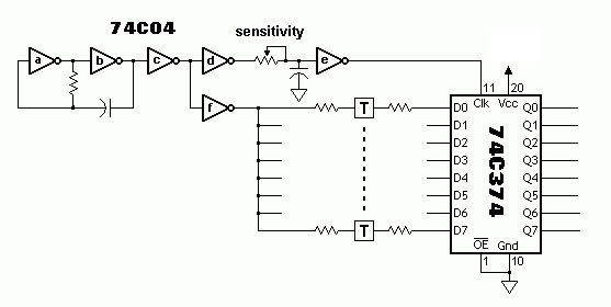
Rather than tinker with the time constant of each touch plate, varying the clock rate, via R2, should provide a Sensitivity adjustment.
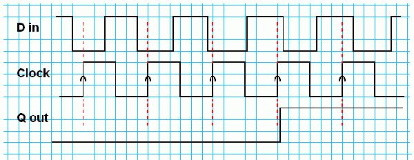
As for circuits that never made it off the breadboard, I've attached one of mine. Resistor and cap values were missing from my original hand-drawn schematic, so experimenting will be necessary. In operation, as long as D is low when Clock goes high, Q will be low. When point "T" -- which should be insulated -- is touched, the rise and fall of D are delayed. When they're delayed long enough that D is high when the rising edge of Clock arrives, Q goes high. To get 8 more contacts only requires another 8-bit latch. 74Cxxx is getting hard to find, but 74HCxxx should work.
There's a similar Ian Fritz circuit here somewhere, but I couldn't find it.
| Description: |
|
| Filesize: |
4.55 KB |
| Viewed: |
3340 Time(s) |

|
| Description: |
|
| Filesize: |
6.62 KB |
| Viewed: |
137 Time(s) |
| This image has been reduced to fit the page. Click on it to enlarge. |

|
_________________
Revenge is a dish best served with a fork... to the eye |
|
|
Back to top
|
|
 |
egasimus

Joined: Feb 11, 2011
Posts: 113
Location: Bulgaria
|
 Posted: Sun Jan 08, 2012 11:58 am Post subject: Posted: Sun Jan 08, 2012 11:58 am Post subject:
|
  |
|
Very interesting! I'm hopefully gonna etch a keyboard pattern on a piece of copper-clad tomorrow as I build my drone box, and later experiment with some of these circuits on the breadboard. I was even considering a hex keyboard - this would be pretty awesome, but hard to do; perhaps your circuit would be the way to go.  |
|
|
Back to top
|
|
 |
|

