| Author |
Message |
Thomas_Henry
Joined: Jul 24, 2009
Posts: 170
Location: N. Mankato, MN
Audio files: 3
|
 Posted: Tue Aug 07, 2012 4:51 pm Post subject:
CMOS ADSR Posted: Tue Aug 07, 2012 4:51 pm Post subject:
CMOS ADSR
Subject description: Includes a built-in light show |
  |
|
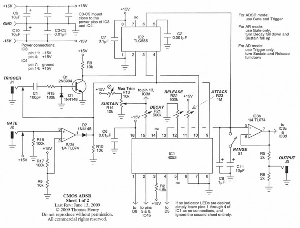
Hello everyone,
Here's the next project. This is a full-featured ADSR with indicator lights. It was really fun to come up with the logic for this---lots and lots of scribbling on scratch paper was required. The hard part, of course, was figuring out how to indicate the Sustain phase. That kept me going for a while.
Note that it can also be used in AR and AD mode with equal ease.
Thomas Henry
| Description: |
|
| Filesize: |
106.93 KB |
| Viewed: |
3127 Time(s) |
| This image has been reduced to fit the page. Click on it to enlarge. |
|
| Description: |
|
| Filesize: |
60.17 KB |
| Viewed: |
2232 Time(s) |
| This image has been reduced to fit the page. Click on it to enlarge. |
|
| Description: |
|
| Filesize: |
62.48 KB |
| Viewed: |
2133 Time(s) |
| This image has been reduced to fit the page. Click on it to enlarge. |
|
|
|
|
Back to top
|
|
 |
andrewF

Joined: Dec 29, 2006
Posts: 1176
Location: australia
Audio files: 4
|
| Posted: Tue Aug 07, 2012 6:09 pm Post subject:
|
|
|
love the Leds for each stage  what a great feature what a great feature
Thanks for sharing Thomas |
|
|
Back to top
|
|
|
v-un-v
Janitor


Joined: May 16, 2005
Posts: 8932
Location: Birmingham, England, UK
Audio files: 11
G2 patch files: 1
|
| Posted: Wed Aug 08, 2012 11:16 am Post subject:
|
|
|
We like lightshows! 
_________________
ACHTUNG!
ALLES TURISTEN UND NONTEKNISCHEN LOOKENPEEPERS!
DAS KOMPUTERMASCHINE IST NICHT FÜR DER GEFINGERPOKEN UND MITTENGRABEN! ODERWISE IST EASY TO SCHNAPPEN DER SPRINGENWERK, BLOWENFUSEN UND POPPENCORKEN MIT SPITZENSPARKSEN.
IST NICHT FÜR GEWERKEN BEI DUMMKOPFEN. DER RUBBERNECKEN SIGHTSEEREN KEEPEN DAS COTTONPICKEN HÄNDER IN DAS POCKETS MUSS.
ZO RELAXEN UND WATSCHEN DER BLINKENLICHTEN. |
|
|
Back to top
|
|
|
thebot
Joined: Mar 07, 2012
Posts: 13
Location: Edinburgh, Scotland
|
| Posted: Wed Aug 08, 2012 12:51 pm Post subject:
|
|
|
| Love the idea of four separate LEDs for each stage. This would make a great first ADSR, would really help new synthesists to visualise the typical ADSR sounds. Lovely design Thomas, thanks for sharing. |
|
|
Back to top
|
|
|
v-un-v
Janitor
Joined: May 16, 2005
Posts: 8932
Location: Birmingham, England, UK
Audio files: 11
G2 patch files: 1
|
| Posted: Wed Aug 08, 2012 1:52 pm Post subject:
|
|
|
Thinking about it, if one made the front panel to this design out of white perspex, and used the LED's (each coloured differently- naturally) to illuminate the front panel.... wouldn't that look nice? 
_________________
ACHTUNG!
ALLES TURISTEN UND NONTEKNISCHEN LOOKENPEEPERS!
DAS KOMPUTERMASCHINE IST NICHT FÜR DER GEFINGERPOKEN UND MITTENGRABEN! ODERWISE IST EASY TO SCHNAPPEN DER SPRINGENWERK, BLOWENFUSEN UND POPPENCORKEN MIT SPITZENSPARKSEN.
IST NICHT FÜR GEWERKEN BEI DUMMKOPFEN. DER RUBBERNECKEN SIGHTSEEREN KEEPEN DAS COTTONPICKEN HÄNDER IN DAS POCKETS MUSS.
ZO RELAXEN UND WATSCHEN DER BLINKENLICHTEN. |
|
|
Back to top
|
|
|
Uncle Krunkus
Moderator

Joined: Jul 11, 2005
Posts: 4761
Location: Sydney, Australia
Audio files: 52
G2 patch files: 1
|
| Posted: Wed Aug 08, 2012 2:38 pm Post subject:
|
|
|
Beautiful!
_________________
What makes a space ours, is what we put there, and what we do there. |
|
|
Back to top
|
|
|
Boogdish
Joined: Sep 21, 2009
Posts: 122
Location: Bloomington, IN
|
| Posted: Wed Aug 08, 2012 6:11 pm Post subject:
|
|
|
| Very cool, thanks for sharing Thomas! This would be a great project to use clear shaft pots with LEDs under them. I agree with "thebot" this would be a great module for showing people new to synthesis how it works. |
|
|
Back to top
|
|
|
AlasdairMoons

Joined: Dec 03, 2011
Posts: 105
Location: East-Belgium
|
|
|
Back to top
|
|
|
Appliancide*

Joined: Jul 04, 2007
Posts: 126
Location: Paul lives in a 1920’s film
|
| Posted: Sun Aug 12, 2012 11:35 am Post subject:
|
|
|
This is great! With all of the logic for the leds worked out already, it shouldn't be too much work to derive "stage high" gates and end out triggers.
_________________
http://appliancide/blogspot.com |
|
|
Back to top
|
|
|
elmegil

Joined: Mar 20, 2012
Posts: 2179
Location: Chicago
Audio files: 16
|
| Posted: Sun Aug 12, 2012 12:11 pm Post subject:
|
|
|
| A relative noob asks: what are "Stage high" Gates? End triggers seem obvious enough.... |
|
|
Back to top
|
|
|
Appliancide*
Joined: Jul 04, 2007
Posts: 126
Location: Paul lives in a 1920’s film
|
| Posted: Sun Aug 12, 2012 1:35 pm Post subject:
|
|
|
I was picturing a gate out that would be held high while the corresponding led was lit, if that makes it easier to grok.
_________________
http://appliancide/blogspot.com |
|
|
Back to top
|
|
|
elmegil
Joined: Mar 20, 2012
Posts: 2179
Location: Chicago
Audio files: 16
|
| Posted: Sun Aug 12, 2012 2:27 pm Post subject:
|
|
|
Ok, that was what I was thinking it must be given context, but I hadn't heard of such things being used/useful before 
Danke! |
|
|
Back to top
|
|
|
AlasdairMoons
Joined: Dec 03, 2011
Posts: 105
Location: East-Belgium
|
|
|
Back to top
|
|
|
blue hell
Site Admin

Joined: Apr 03, 2004
Posts: 24673
Location: The Netherlands, Enschede
Audio files: 330
G2 patch files: 320
|
| Posted: Wed Aug 15, 2012 6:44 am Post subject:
|
|
|
These are switches in the connectors which are opened when a plug is put in.
_________________
Jan
also .. could someone please turn down the thermostat a bit.

9 3 4 .. erm .. not 13 then? .. hmm, ah eight! .. yeah yeah as in 8647 .. 47 is an 88 .. pwew .. numbles! |
|
|
Back to top
|
|
|
schmidtc
Joined: May 16, 2009
Posts: 34
Location: Boston
|
| Posted: Tue Aug 21, 2012 10:23 am Post subject:
|
|
|
Thanks TH! Further proof you are the master of functionality and simplicity in design. A few questions. . .
1.) Output is 0 to +5V log response?
2.) The switching jack on the trigger in allows gate only adsr?
3.) What's the range switch do?
4.) Any info on the times of the envelope stages?
If this is too many questions, "build it and see" is an acceptable response  |
|
|
Back to top
|
|
|
fonik

Joined: Jun 07, 2006
Posts: 3950
Location: Germany
Audio files: 23
|
| Posted: Tue Sep 11, 2012 6:31 am Post subject:
|
|
|
| schmidtc wrote: | | 2.) The switching jack on the trigger in allows gate only adsr? |
that's how i understand it, and the gate input is normalled to 15V to aloow trigger only operation.
| Quote: | | 3.) What's the range switch do? |
changes the timing cap value to allow for slower envelopes.
re stage gates and end trigger:
i thought of adding another TL074 to buffer these outputs.
the end trigger would occure as soon as the ADSR goes into the release stage, otherwise one would have to add an additional comparator.
is an end trigger useful when in ADSR mode?
_________________

cheers,
matthias
____________
Big Boss at fonitronik
Tech Buddy at Random*Source |
|
|
Back to top
|
|
|
marvkaye
Joined: Mar 14, 2011
Posts: 225
Location: Fla
|
| Posted: Wed Sep 12, 2012 10:36 pm Post subject:
|
|
|
As much as I'd prefer a nice double-sided through-hole plated PCB for this incredibly cool EG (thank you Thomas, you never fail to amaze...) I confess that I'm not up to the task and so decided to take the coward's way out and create a strip board layout instead. After a few false starts I finally managed to come up with a reasonable design, finished size is just under 1.5 X 4.5 inches (37 x 114mm for those of you who prefer metric) and thought I'd share it here for anyone who's itching to build one of these in a more permanent format than breadboard.


Tomorrow I'll see about getting another picture up with all of the panel connections (green squares) labelled... please note, I have not physically built this yet but did double-check it for accuracy using the test mode in LochMaster, which actually works pretty well. I'll give it another once over tomorrow with less tired eyes, just to be sure. Please let me know if you spot any glaring errors. I hope you find it useful.
<marv>
(edit... I almost forgot... the connection between IC1 pin 2 and IC4 pin 5 needs to be done with a jumper wire that's not shown on the stripboard. )
(edit 2... here's the panel wiring map...

<m>
Last edited by marvkaye on Thu Sep 13, 2012 7:42 am; edited 1 time in total |
|
|
Back to top
|
|
|
elmegil
Joined: Mar 20, 2012
Posts: 2179
Location: Chicago
Audio files: 16
|
| Posted: Thu Sep 13, 2012 5:12 am Post subject:
|
|
|
| For Lochmaster, on the rear view, the cuts are obvious enough, but what are all the circles? They don't seem to correspond to the pins coming through the board, but I confess I haven't counted out to triple check that. |
|
|
Back to top
|
|
|
-minus-
Joined: Oct 26, 2008
Posts: 787
Audio files: 13
|
| Posted: Thu Sep 13, 2012 5:57 am Post subject:
|
|
|
I think the circles are solder. The board is flipped bottom to top rather than left to right. I didn't know the circuit layout could be tested before building. That's a good feature.
It's probably just me, but I would be trying to make the layout fit in just over half that space. I'd try not to run jumpers under the IC's (or over as I have seen before elsewhere). I never run components diagonally. I don't even like having them horizontally orientated, unless to do otherwise will increase the footprint substantially. Anyway, I hope it functions first time for you. That's always a nice feeling. |
|
|
Back to top
|
|
|
elmegil
Joined: Mar 20, 2012
Posts: 2179
Location: Chicago
Audio files: 16
|
| Posted: Thu Sep 13, 2012 6:25 am Post subject:
|
|
|
| Ah, yes, top to bottom lines up. Thank you |
|
|
Back to top
|
|
|
marvkaye
Joined: Mar 14, 2011
Posts: 225
Location: Fla
|
| Posted: Thu Sep 13, 2012 9:11 am Post subject:
|
|
|
Bump to point back to the edit above where I added the panel wiring map to the strip board layout post.
| -minus- wrote: | | I didn't know the circuit layout could be tested before building. That's a good feature. |
Yeppers, it's very cool... the "tester" lights up all the components and strips connected to its "probe". Really aids in the greenlining process. |
|
|
Back to top
|
|
|
marvkaye
Joined: Mar 14, 2011
Posts: 225
Location: Fla
|
| Posted: Thu Sep 13, 2012 10:26 am Post subject:
|
|
|
| elmegil wrote: | | For Lochmaster, on the rear view, the cuts are obvious enough, but what are all the circles? They don't seem to correspond to the pins coming through the board, but I confess I haven't counted out to triple check that. |
Just FYI, all of the "cuts" that are centered on holes are actually done with an 1/8" drill bit. Stick it in a pin vise, put the tip in the proper hole and give it a couple twists... pretty quick and painless. The narrow cuts between holes I do with a thin saw blade in a Dremel... they can be done with a razor knife but I find the mini-saw approach to be much more controllable and yields superior results. JIC you're thinking about getting started w/ strip board yourself. Search around and take a look at some of Uncle Krunkus's examples... he's a real artist with it.
<m> |
|
|
Back to top
|
|
|
elmegil
Joined: Mar 20, 2012
Posts: 2179
Location: Chicago
Audio files: 16
|
| Posted: Thu Sep 13, 2012 10:41 am Post subject:
|
|
|
Right, I built minus' TR-808 drum voice stripboard, and figured that out pretty quickly (about the drill bit). Although my stripboard must be slightly wider or something because I still had to go back and clean up with an exacto (aka razor knife).
I've never had ANY luck using a dremel for anything of any precision, so I think I'll stick with the knife for the narrow cuts too Cutting wheels in particular always seem to fly apart at the worst possible moment, and I don't have any kind of reciprocating dremel or attachment. Maybe a teensy diamond head, who knows, but I'd probably end up cutting 3 strips instead of just one. |
|
|
Back to top
|
|
|
-minus-
Joined: Oct 26, 2008
Posts: 787
Audio files: 13
|
| Posted: Thu Sep 13, 2012 11:15 am Post subject:
|
|
|
Actually, I think that was slacker I think who originally posted that stripboard of the 808 kick drum.
Yes, if it weren't for uncle krunkus and his wsg stripboard, I may never have ended up on the stripboard path.
A 3MM drill bit works for me, but I guess you could go up to 4MM if it wasn't wide enough to cut the width of the tracks.
Anyway, I wouldn't mind giving this circuit a go! |
|
|
Back to top
|
|
|
wmonk
Joined: Sep 15, 2008
Posts: 529
Location: Enschede, the Netherlands
Audio files: 15
|
| Posted: Sat Sep 15, 2012 5:00 am Post subject:
|
|
|
Have to say this is a beautiful design. Wow, so simple
Thomas did it again!
Now I'm going to build one on stripboard
Perhaps a nice add-on which would be very unique is to connect a buffer to the same place as the LEDs, that way you have gate outs depending on the stage.
Edit, oh, I forgot to read all comments again, it was already mentioned.
_________________
Weblog! |
|
|
Back to top
|
|
|
|

 Forum index » DIY Hardware and Software » Thomas Henry designs
