| Author |
Message |
radfaraf
Joined: May 02, 2005
Posts: 18
Location: USA
|
 Posted: Tue May 10, 2005 1:54 pm Post subject:
Ceramic Chip Capacitors? Posted: Tue May 10, 2005 1:54 pm Post subject:
Ceramic Chip Capacitors? |
  |
|
I ordered some ceramic chip capacitors from mouser because some of the recommended ones weren't in stock. Most of my electronics knowledge comes from what I learned in physics and having just finished an electronics class. I was in a hurry so figured they do the job. They look a bit strange  though. So what are these used for? and how would I wire one of these if I wanted to ? though. So what are these used for? and how would I wire one of these if I wanted to ?
Picture below, this is 5 capacitors according to the label on the packaging.
 |
|
|
Back to top
|
|
 |
jksuperstar

Joined: Aug 20, 2004
Posts: 2503
Location: Denver
Audio files: 1
G2 patch files: 18
|
| Posted: Tue May 10, 2005 2:15 pm Post subject:
|
|
|
Those caps are "Surface Mount"...they aren't intended to be used as the other kind which you probably intended, called "Through Hole". As the name implies, thru hole have long leads that go through the mounting holes, then soldered. Surface mount are intended to be used with a solder pad, which has no hole that goes through the board. Do you know if it is a "1206", "804", or "603" size? These are just the sizes of the surface mount device, with "1206" being the largest. It's not important, but if I knew I could feel either more sympathy or courage for you:) They look like 1206, which should make your life easier.
So don't dispare! You have 2 options (as far as I've performed)...you can either lay the Surface Mount cap over the holes where the caps should be mounted...if they line up, you could carefully solder them down. It isn't necessary that something goes through the mounting hole (the hole itself is lined with copper, so it doesn't matter which side of the board you put the cap, choose the more accessible side!). Do this by 1st putting *a very little* solder down on the mounting holes, 2nd hold your cap over the new solder beads (make sure no solder can short across the two ends), and finally, while holding the cap in place, touch the solder with your soldering iron at each end of the cap. It should take hold in a second or so, and that's it. The drawback to this method is a solder bridge can form under the cap if youuse too much solder.
The other option is to 1st solder some wires leading from each end of the cap, then as a unit stick the "leads" through the mounting holes, and solder into place as you would a regular through-hole type cap. The only draw back to this method, is that sometimes the heat will travel up the wire, melt the solder attached to the cap, and the cap falls off the wire.
Be careful but quick while soldering these parts. If you heat them up too much, the silver end caps tend to come off, and the part becomes useless.
good luck! |
|
|
Back to top
|
|
|
radfaraf
Joined: May 02, 2005
Posts: 18
Location: USA
|
| Posted: Tue May 10, 2005 3:05 pm Post subject:
|
|
|
That doesn't sound like fun, I got 4 different capacitors like this. Two of them say 0603 on them and the other two 0805. I'm just confused as to which hole would be used as input of current and which for the ouput of it? For 5 capacitors there is only 4 holes. Either way these are cheap so i'll just get myself the through hole ones.  I'm starting construction this weekend after I finish my finals at college. I'm starting construction this weekend after I finish my finals at college.
Last edited by radfaraf on Tue May 10, 2005 3:13 pm; edited 2 times in total |
|
|
Back to top
|
|
|
jksuperstar
Joined: Aug 20, 2004
Posts: 2503
Location: Denver
Audio files: 1
G2 patch files: 18
|
| Posted: Tue May 10, 2005 3:08 pm Post subject:
|
|
|
| almost all surface mount caps are not sensitive to + or - orientation. 0603 might be tough, especially if you don't have a small soldering gun designed for it. Happy hunting... |
|
|
Back to top
|
|
|
radfaraf
Joined: May 02, 2005
Posts: 18
Location: USA
|
| Posted: Tue May 10, 2005 3:14 pm Post subject:
|
|
|
Since we are on capacitors I have another questions.  Can I tell from the PC Board layout pictures where to plugin the positive and negative ends of the capacitors? I can tell off of the schematics but I'm wondering if the PC Board layout is made in way that also easily tells this, since it's much easier constructing from this. Can I tell from the PC Board layout pictures where to plugin the positive and negative ends of the capacitors? I can tell off of the schematics but I'm wondering if the PC Board layout is made in way that also easily tells this, since it's much easier constructing from this. |
|
|
Back to top
|
|
|
jksuperstar
Joined: Aug 20, 2004
Posts: 2503
Location: Denver
Audio files: 1
G2 patch files: 18
|
| Posted: Tue May 10, 2005 5:05 pm Post subject:
|
|
|
What type of capacitor? Are they actually labelled on the schematic with a "+" one one side?
Many types of capacitor (including ceramic) are non-polarized, meaning they don't care which side is positive and which is negative.
Electrolytics and tantulums are two common polarized types.
The ceramics, epoxy, and "Poly" (polyester, polystyrene, etc) are all (most often) non-polarized.
If you ever come across an "NP0" cap, it does not mean "Non-Polarized"! It describes the capacitor as being stable over tempurature. |
|
|
Back to top
|
|
|
radfaraf
Joined: May 02, 2005
Posts: 18
Location: USA
|
| Posted: Tue May 10, 2005 5:20 pm Post subject:
|
|
|
Got lots of kinds.
Xicon Radial Electrolytic. They are nice soda can shaped with negative symbol on the shorter lead.
Monolythic Ceramic Radial. These look non-polarized to me because of same size leads.
Radial Polyester Film. One lead shorter than the other. Rectangular shaped.
Kemet Molded Radial Ceramic. Same size leads |
|
|
Back to top
|
|
|
dnny

Joined: Mar 12, 2005
Posts: 519
Location: Helsinki, Finland
Audio files: 8
|
| Posted: Thu May 12, 2005 2:34 am Post subject:
|
|
|
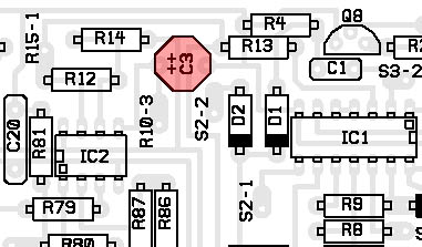
| radfaraf wrote: | | I can tell off of the schematics but I'm wondering if the PC Board layout is made in way that also easily tells this, since it's much easier constructing from this. |
Hi radfaraf
the following caps are polarization critical
C16 & C18 those are most likely the soda can shaped ones rated at 100uF
and C3 tantalum cap rated at 2uF
in the Printed Circuit Parts Legend positive lead are indicated.
hope this helps
daniel
| Description: |
|
| Filesize: |
55.56 KB |
| Viewed: |
9109 Time(s) |

|
| Description: |
|
| Filesize: |
46.59 KB |
| Viewed: |
9106 Time(s) |
|
|
|
|
Back to top
|
|
|
radfaraf
Joined: May 02, 2005
Posts: 18
Location: USA
|
|
|
Back to top
|
|
|
radfaraf
Joined: May 02, 2005
Posts: 18
Location: USA
|
| Posted: Sun May 15, 2005 6:59 am Post subject:
|
|
|
Putting it the capacitors that I have now. I not sure about C14 though. For this capacitor I have one that has one lead shorter than the other. I think I need to hook the longer(positive) one to R91 and R88 but I am not sure if that is correct.
Here's the schematic for the part with C14.
 |
|
|
Back to top
|
|
|
|

 Forum index » DIY Hardware and Software » MusicFromOuterSpace.com designs by Ray Wilson
