| Author |
Message |
dub halley

Joined: Dec 22, 2010
Posts: 26
Location: Rennes, FRANCE
|
 Posted: Mon May 11, 2015 12:46 pm Post subject: Posted: Mon May 11, 2015 12:46 pm Post subject:
|
  |
|
| sneakthief wrote: | | Offbeat: play a beat every on step that trigger #1 does NOT play. |
ok, I have to test 
| Quote: | | Re. My extra jacks: as I wrote above in the front panel description |
Excuse me I hadn't see this sentence .... 
| Quote: | | adding another 4 analog/digital ins for future CV/gate usage. for CV control, I recommend using 2x 1N5819's per CV input. I'll draw a schematic for that later. |
To add CV/Gate .... Means the CV in from LFO (for example) should go to Analog in of the nano ?
The diodes 1N5819 are for a power protection, did you use them in zener mode ?
| Quote: | | ...I put A, B, C & D as placeholders for whatever inputs make sense. I decided to set mine to gate inputs for density and length" |
Great job ...
Really ... Thanks for sharing and helping   |
|
|
Back to top
|
|
 |
sneakthief

Joined: Jul 24, 2006
Posts: 569
Location: Berlin
|
|
|
Back to top
|
|
|
dub halley
Joined: Dec 22, 2010
Posts: 26
Location: Rennes, FRANCE
|
| Posted: Mon May 25, 2015 7:13 am Post subject:
|
|
|
Thanks for the input protection 
But I can't test because I've a problem ...
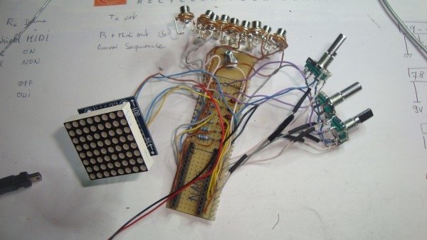
When everything was on a prototyping board, all was working good.
And I wanted to put everything in a eurorack module.
I drill my frontplate and put all the component inside.
Then the module worked about one minute and freeze.
I restarted it and the matrix flash all the led's one second and stop.
And then, no more action...
I tried with another arduino nano, and it was the same, work one minute and freeze.
Then I try to restart and it just turn on the led one second ... that's all
I tried with all the components out of the module because I thought the groung with the plate was bad,.... no more result ??
I tried the arduino with the code matrix demo, and the matrix plugin.
It work !! so the Nano was not dead ... or maybe only the output for the matrix ??
I put the euclidean code to check, and the leds flash one seconds and stop lightning ....
I don't know ....
I checked all the welding point and the connexion, all seem to be good and at the good place...
What a mystery ....  |
|
|
Back to top
|
|
|
sneakthief
Joined: Jul 24, 2006
Posts: 569
Location: Berlin
|
| Posted: Mon May 25, 2015 4:42 pm Post subject:
|
|
|
Oops! I noticed the schematic image is an older version. I'll post the new one tomorrow - the switches should be:
+5v -- 15k -- switch -- 15k -- switch -- 15k -- switch -- 15k -- GND
dub halley: try clearing the eeprom with this code and then reloading the euclidean program...
| Code: | /*
* EEPROM Clear
*
* Sets all of the bytes of the EEPROM to 0.
* This example code is in the public domain.
*/
#include <EEPROM>
void setup()
{
// write a 0 to all 512 bytes of the EEPROM
for (int i = 0; i < 1024; i++)
EEPROM.write(i, 50);
// turn the LED on when we're done
digitalWrite(13, HIGH);
}
void loop()
{
}
|
Otherwise, check all your wiring again and compare it to the pictures you posted earlier in this thread.
_________________
Sneak-Thief - raw electrofunk |
|
|
Back to top
|
|
|
sneakthief
Joined: Jul 24, 2006
Posts: 569
Location: Berlin
|
| Posted: Tue May 26, 2015 5:27 am Post subject:
|
|
|
Once again, here's the corrected schematic:

I've updated the previous posts as well.
_________________
Sneak-Thief - raw electrofunk |
|
|
Back to top
|
|
|
dub halley
Joined: Dec 22, 2010
Posts: 26
Location: Rennes, FRANCE
|
|
|
Back to top
|
|
|
sneakthief
Joined: Jul 24, 2006
Posts: 569
Location: Berlin
|
| Posted: Tue May 26, 2015 2:11 pm Post subject:
|
|
|
EC11 encoders shouldn't have any issues.
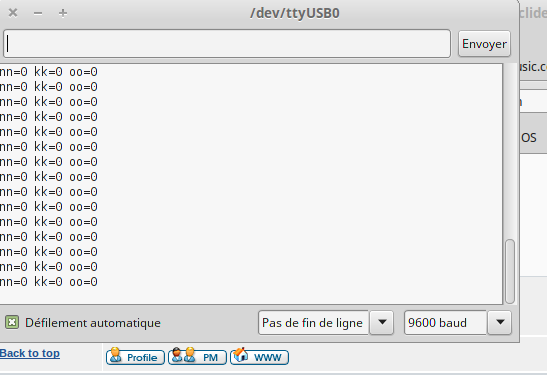
The debugger lets you verify your encoder movements to see if they're working OK:
Set it to #2 then set your Arduino serial port monitor to 9600bps:
| Quote: |
#define debug 2 // 0 = normal 1 = (internal clock) 2= SerialDump
|
| Quote: |
// DEBUG PULSE TRIGGER & print out
if (debug >0 && time-last_sync > 250){
Sync();
if (debug ==2){
Serial.print ("nn=");
Serial.print (nn);
Serial.print (" kk=");
Serial.print (kk);
Serial.print (" oo=");
Serial.println (oo);
}
}; |
_________________
Sneak-Thief - raw electrofunk |
|
|
Back to top
|
|
|
dub halley
Joined: Dec 22, 2010
Posts: 26
Location: Rennes, FRANCE
|
|
|
Back to top
|
|
|
sneakthief
Joined: Jul 24, 2006
Posts: 569
Location: Berlin
|
|
|
Back to top
|
|
|
dub halley
Joined: Dec 22, 2010
Posts: 26
Location: Rennes, FRANCE
|
|
|
Back to top
|
|
|
dub halley
Joined: Dec 22, 2010
Posts: 26
Location: Rennes, FRANCE
|
|
|
Back to top
|
|
|
sneakthief
Joined: Jul 24, 2006
Posts: 569
Location: Berlin
|
| Posted: Thu May 28, 2015 7:44 am Post subject:
|
|
|
Dub Halley - I'm sorry to hear it didn't work out so far. So far this code has been successfully tested with a few different encoders.
It's very hard for me to speculate here, but it's possible the batch of encoders you got from eBay simply aren't working well with the encoder library.
The encoder behaviour you mentioned when rotating it quickly is definitely suspicious.
This could be from encoders that aren't built well enough and put out "noisy" signals.
Also, I suppose that's the nature of these eBay components... I've noticed that you never know exactly what you'll get as parts can vary between shipments.
Also, does anything happen when you push the encoder buttons? The different LED's corresponding to each of the 3 channels should turn on depending on which button you press.
If you're absolutely sure that your wiring is OK and you don't have any ground problems, try out different encoders.
Conrad.fr has this one:
http://www.conrad.fr/ce/fr/product/453377/Encodeur-TT-Electronics-AB-9302520100-5-VDC-001-A-Positions-de-commutation-20-360-1-pcs?ref=searchDetail
_________________
Sneak-Thief - raw electrofunk |
|
|
Back to top
|
|
|
dub halley
Joined: Dec 22, 2010
Posts: 26
Location: Rennes, FRANCE
|
| Posted: Thu Jun 04, 2015 2:51 pm Post subject:
|
|
|
Hello
Sorry for the lag ...
| sneakthief wrote: | | Dub Halley - I'm sorry to hear it didn't work out so far. |
Don't be worry it's not your fault
More difficult a DIY module is to build, more fun when we('ll) have to use it with the modular 
I read a good article in this wonderful french review : http://www.hackable.fr/
There is inside : encoder, how it's work.
Here a picture from the web.

I add an 100nF Capa from the switch to gnd and to get an anti rebound switch.
It worked a little bit better when I tried with the example of the encoder library.
But it's still not exact ...
I command 6 of the conrad encoder ... we'll see ...???
| Quote: | | Also, does anything happen when you push the encoder buttons? The different LED's corresponding to each of the 3 channels should turn on depending on which button you press. |
I cannot do a video tonight, I'll show you tomorrow.
| Quote: | | If you're absolutely sure that your wiring is OK and you don't have any ground problems, |
I'll show you, I did a second circuit with another Arduino and stuff on a board and it's the same result ...
The circuit work like the first one ...
Very strange ...
May be I catch a ZombieDuino ?? 
|
|
|
Back to top
|
|
|
tombola
Joined: Mar 11, 2005
Posts: 84
Location: London
Audio files: 3
G2 patch files: 9
|
| Posted: Thu Jun 18, 2015 3:25 pm Post subject:
|
|
|
WOW, I just saw this. Amazing, so fantastic that you've got it working so well.
_________________
http://www.musicthing.co.uk/ |
|
|
Back to top
|
|
|
bamboombaps
Joined: Oct 23, 2015
Posts: 66
Location: Glasgow
|
| Posted: Fri Jan 08, 2016 5:21 pm Post subject:
|
|
|
im falling at the first hurdle-
error compiling?
edit- hadnt installed libraries.
BUT now im getting this-
edit edit- all good hadnt installed correct driver for my knockoff nano  |
|
|
Back to top
|
|
|
Ray_Ketamu
Joined: Nov 03, 2014
Posts: 48
Location: Germany
|
|
|
Back to top
|
|
|
Ray_Ketamu
Joined: Nov 03, 2014
Posts: 48
Location: Germany
|
|
|
Back to top
|
|
|
Ray_Ketamu
Joined: Nov 03, 2014
Posts: 48
Location: Germany
|
|
|
Back to top
|
|
|
bamboombaps
Joined: Oct 23, 2015
Posts: 66
Location: Glasgow
|
| Posted: Tue Jan 12, 2016 5:16 am Post subject:
|
|
|
| not sure anyone pops by here anymore- shame its a great project but jsut a little beyond my abilities- i will do it but it will take longer than with a little help from the electro-music friends! |
|
|
Back to top
|
|
|
LFLab
Joined: Dec 17, 2009
Posts: 497
Location: Rosmalen, Netherlands
|
| Posted: Tue Jan 12, 2016 6:16 am Post subject:
|
|
|
Still need to retry this, I cobbled something together, but got erratic behaviour of the matrix led display. Threw it in the dedicated "long term, someday maybe, work in progress" bin
It's this thread on muffwiggler, right? Euclidean Sequencer
Tombola initiated the thread, but Sneak-thief posted his version a little later in the thread. |
|
|
Back to top
|
|
|
bamboombaps
Joined: Oct 23, 2015
Posts: 66
Location: Glasgow
|
| Posted: Fri Jun 03, 2016 6:50 pm Post subject:
|
|
|
after a previous aborted attempt i came back to this project and ive spent so many hours today trying to prep a shady nano to get this working.
i just have to share the following- if anyone has issues getting the arduino program to talk to their chosen board, please visit codebender.cc and this takes 10 mins, mostly automated.
at last i can start the build proper! but tomorrow. first i need to sleep  |
|
|
Back to top
|
|
|
sneakthief
Joined: Jul 24, 2006
Posts: 569
Location: Berlin
|
| Posted: Tue Jun 21, 2016 5:51 am Post subject:
|
|
|
First off, I found a bunch more bugs in Tombola's code & wiring guide. I'll post a revised version in the next couple of days.
1. Power consumption & led brightness
The brightness can be set between 0 at 16. When it's 0, it's actually pretty readable and comfortable.
Some power usage that I've observed:
60-80mA / 5V at brightness 0
120-160mA / 5V at brightness 8
140-180mA / 5V at brightness 16
I also fixed a bug with the startup and sleep animations that overrides the brightness variable.
2. Added a pulldown resistor
There should be a 10k pulldown resistor that connects A2 to ground. The voltage divider that the 3 switches use to select channel leaves the analog input floating when not pressed and makes the buttons unreliable.
I also modified the analog readings to match the new button values.
3. eeprom corruption causes arduino to go blank
The eeprom sometimes gets corrupted due to the way it's written. I'm making a more robust eeprom reset procedure. In the meantime, use this code to clear your eeprom - afterwards reprogram it with the euclidean code:
| Quote: |
/*
* EEPROM Clear
*
* Sets all of the bytes of the EEPROM to 0.
* This example code is in the public domain.
*/
#include <EEPROM>
void setup()
{
// write a 0 to all 512 bytes of the EEPROM
for (int i = 0; i < 1024; i++)
EEPROM.write(i, 50);
// turn the LED on when we're done
digitalWrite(13, HIGH);
}
void loop()
{
} |
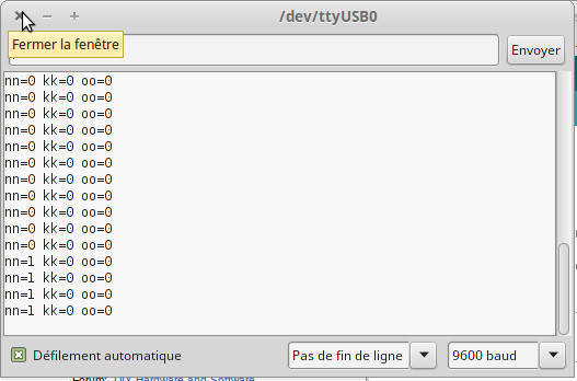
4. Weird characters like those shown in earlier posts
Most matrices have 2 connectors: one for input one for output. Make sure to connect the arduino to the connector on the matrix that has the DIN pin and not the DOUT.
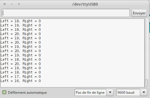
5. Test your encoders!
Use this encoder test program to see if your encoders are connected properly. I modified the original "TwoKnobs" sketch match the project using the arduino Serial Monitor
| Quote: | /* Encoder Library - TwoKnobs Example
* http://www.pjrc.com/teensy/td_libs_Encoder.html
*
* This example code is in the public domain.
*/
#include <Encoder>
// Change these pin numbers to the pins connected to your encoder.
// Best Performance: both pins have interrupt capability
// Good Performance: only the first pin has interrupt capability
// Low Performance: neither pin has interrupt capability
Encoder knobLeft(10, 9);
Encoder knobRight(8, 7);
Encoder knob3(6, 5);
// avoid using pins with LEDs attached
void setup() {
Serial.begin(9600);
Serial.println("Three Knobs Encoder Test:");
}
long positionLeft = -999;
long positionRight = -999;
long position3 = -999;
void loop() {
long newLeft, newRight, new3;
newLeft = knobLeft.read();
newRight = knobRight.read();
new3 = knob3.read();
if (newLeft != positionLeft || newRight != positionRight || new3 != position3 ) {
Serial.print("1 = ");
Serial.print(newRight);
Serial.print(", 2 = ");
Serial.print(newLeft);
Serial.print(", 3 = ");
Serial.print(new3);
Serial.println();
positionLeft = newLeft;
positionRight = newRight;
position3 = new3;
}
// if a character is sent from the serial monitor,
// reset both back to zero.
if (Serial.available()) {
Serial.read();
Serial.println("Reset all knobs to zero");
knobLeft.write(0);
knobRight.write(0);
knob3.write(0);
}
} |
_________________
Sneak-Thief - raw electrofunk |
|
|
Back to top
|
|
|
sneakthief
Joined: Jul 24, 2006
Posts: 569
Location: Berlin
|
| Posted: Tue Jun 21, 2016 5:53 am Post subject:
|
|
|
Code now on github: https://github.com/sneak-thief/Tombola_Euclidean_Sequencer
Latest schematic:

Hardware updates:
- tested as working with this LED display from Bay:
http://www.ebay.com/itm/131497841320
- 10k pulldown resistor to GND on the A2 switch inputs
- Switch inputs go to AREF instead of the normal 5V
- I now use 10K resistors because they're more common and more likely to be already on hand. If you're using 15K resistors, it's easy to change the code to make it compatible.
- You can substitute 220R resistors instead of 200R resistors if that's more convenient..
Software updates:
- Added more error checking for eeprom reads / values to reduce risk of crashes
- Fixed brightness define bug which prevented brightness from being set
- For those who tried the previous code and only saw a blank screen, Tombola had programmed the screen to only turn on after the first trigger, otherwise it would stay in "sleep mode". The screen also goes into sleep mode after several minutes of inactivity.
- I changed the default mode to automatically run from a fixed speed internal clock until it receives a pulse, then it only triggers externally.
_________________
Sneak-Thief - raw electrofunk |
|
|
Back to top
|
|
|
Grumble

Joined: Nov 23, 2015
Posts: 1320
Location: Netherlands
Audio files: 30
|
| Posted: Thu Jun 23, 2016 12:54 am Post subject:
|
|
|
I've made something like this, but in my module the LEd's are "falling" down instead of going fron left to right.
Boy, the troubles I had to get this done...
https://youtu.be/eUIsoyMTK1E |
|
|
Back to top
|
|
|
kitchen lab
Joined: Feb 16, 2016
Posts: 4
Location: Belgium
|
| Posted: Thu Aug 11, 2016 7:50 am Post subject:
|
|
|
Hello sneakthief!
Thank you for your work on this project. With your latest version (0.7) and some eprom clearing, I finally got it working!!
Only issue now is the channel selection. What do you mean with | Quote: | | Switch inputs go to AREF |
Many thanks, again |
|
|
Back to top
|
|
|
|

 Forum index » DIY Hardware and Software