| Front Page | Radio | Media | Forum | Wiki | Links |

and electronic music
|
|
Dedicated to
experimental electro-acoustic and electronic music |
|
|
|
|
|||||||||
 Forum index » DIY Hardware and Software » Circuit Bending Forum index » DIY Hardware and Software » Circuit Bending |
|
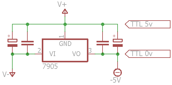
using negative regulator to pull up ground?
|
 
|
Moderators: dnny, v-un-v
Page 1 of 1 [5 Posts] |
View unread posts View new posts in the last week Mark the topic unread :: View previous topic :: View next topic |
| Author | Message | |||||||||||||||||||
|---|---|---|---|---|---|---|---|---|---|---|---|---|---|---|---|---|---|---|---|---|
noto
 Joined: Nov 05, 2009 Posts: 24 Location: portland |
|
|||||||||||||||||||
|
|
||||||||||||||||||||
JovianPyx
 Joined: Nov 20, 2007 Posts: 1988 Location: West Red Spot, Jupiter Audio files: 224 |
|
|||||||||||||||||||
|
|
||||||||||||||||||||
|
noto
Joined: Nov 05, 2009 Posts: 24 Location: portland |
|
|||||||||||||||||||
|
|
||||||||||||||||||||
|
JovianPyx
Joined: Nov 20, 2007 Posts: 1988 Location: West Red Spot, Jupiter Audio files: 224 |
|
|||||||||||||||||||
|
|
||||||||||||||||||||
|
noto
Joined: Nov 05, 2009 Posts: 24 Location: portland |
|
|||||||||||||||||||
|
|
||||||||||||||||||||
|
|
Moderators: dnny, v-un-v
Page 1 of 1 [5 Posts] |
View unread posts View new posts in the last week Mark the topic unread :: View previous topic :: View next topic |
|
Forum index » DIY Hardware and Software » Circuit Bending |
|
You cannot post new topics in this forum You cannot reply to topics in this forum You cannot edit your posts in this forum You cannot delete your posts in this forum You cannot vote in polls in this forum You cannot attach files in this forum You can download files in this forum |