| Author |
Message |
petegaggs
Joined: Jan 04, 2018
Posts: 23
Location: Cambridge, UK
Audio files: 1
|
 Posted: Wed Mar 21, 2018 1:34 pm Post subject: Posted: Wed Mar 21, 2018 1:34 pm Post subject:
|
  |
|
| synthjakk wrote: | Thank you again, you are being very helpful. I have built the circuit and am just waiting for the 5 DIN connector to arrive so that I can test it.
Something that I am trying to work out is the frequency range that is outputted by the microcontroller PWM out. the spread sheet shows a range between say 300 to 30,000 values sent to the timer.
The timer is prescaled from 16Mhz to 2MHz.
So what frequency would the PWM output with the value 300 say ? |
If you loaded the timer with 300, the timer would run for 301 timer clock periods, e.g. 301 x (1/2MHz) = 150.5 microseconds.
The timer block is set up to toggle the OC1A pin every time the timer reaches 0, so the period of the signal given out on the pin will be double that, e.g. 301 microseconds, or a frequency of 3322.25Hz. Smaller values in the timer register give higher note frequencies.
Hope this helps.
Pete |
|
|
Back to top
|
|
 |
synthjakk
Joined: Feb 12, 2018
Posts: 20
Location: UK
|
| Posted: Fri Mar 23, 2018 9:23 am Post subject:
|
|
|
That makes sense, so I guess that the max value that the timer can be loaded with is 65535. Giving a frequency of 15.23Hz. And a maximum frequency would be 1Mhz (1 loaded in timer). so 300, would produce a duty cycle of (301/65536) x 100 = 0.46%.
Looking at your photo, did you only use 2 Electrolytic capacitors for the 7805 regulator, and the rest Ceramic? Im having a issue with the build. Thanks ! 
Last edited by synthjakk on Fri Mar 23, 2018 10:01 am; edited 1 time in total |
|
|
Back to top
|
|
|
petegaggs
Joined: Jan 04, 2018
Posts: 23
Location: Cambridge, UK
Audio files: 1
|
| Posted: Fri Mar 23, 2018 9:48 am Post subject:
|
|
|
| synthjakk wrote: | That makes sense, so I guess that MAX that the timer could run for is 65.535 microseconds, giving a frequency of 15,259Hz. Therefore am I right in thinking that the duty cycle can be calculated from this?
Looking at your photo, did you only use 2 Electrolytic capacitors for the 7805 regulator, and the rest Ceramic? Im having a issue with the build. Thanks ! |
Yes, about 15Hz sounds right. The duty cycle is always 50%, because the pin toggles state each time the timer wraps round.
the prototype in the photo was not built exactly the same as the schematic I published. In the prototype, I used the arduino's regulator to supply 5V, the schematic shows this sourced from a 7805. Either method can be used, as I explained before.
The 2 electrolytics in the photo are the ones associated with the LMC7660 inverter.
Everything else was ceramic, including the integrator capacitor, though polypropelene would have been better (better tolerance than ceramics).
If you have a 7805, it just needs a bit of decoupling on the input and output. Ideally ceramic, 100nF or larger if you have available. But electrolytic would probably be fine here |
|
|
Back to top
|
|
|
synthjakk
Joined: Feb 12, 2018
Posts: 20
Location: UK
|
| Posted: Sun Mar 25, 2018 12:33 pm Post subject:
|
|
|
| Interesting thought, how does the oscillator manage to turn off the MIDI notes without the gate? is the gate there to connect to a future VCA? or does the gate On and Off work within the microcontroller? |
|
|
Back to top
|
|
|
petegaggs
Joined: Jan 04, 2018
Posts: 23
Location: Cambridge, UK
Audio files: 1
|
| Posted: Mon Mar 26, 2018 9:35 am Post subject:
|
|
|
| synthjakk wrote: | | Interesting thought, how does the oscillator manage to turn off the MIDI notes without the gate? is the gate there to connect to a future VCA? or does the gate On and Off work within the microcontroller? |
The oscillator won't turn off the notes, it is always on, the gate signal is intended to be connected to an external envelope generator which would in turn control a VCA. |
|
|
Back to top
|
|
|
synthjakk
Joined: Feb 12, 2018
Posts: 20
Location: UK
|
| Posted: Wed Mar 28, 2018 11:32 am Post subject:
|
|
|
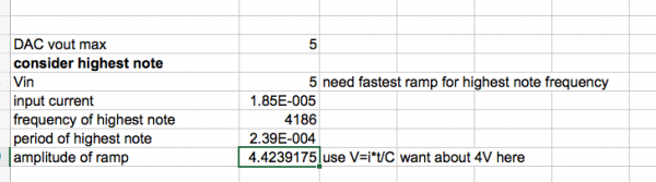
Ahhh I see, I will have to have a look for a simple design that will allow me to use this device on its own.
I am still a bit confused with the DAC max ramp equation. You seem to have gone for the 5 octave range (which is what I want to achieve). but the max ramp equation uses the time period of the MIDI note 108 (4186Hz). So I thought that maybe you did this before you decided to reduce the octave range? and that maybe by using MIDI note 84 (1045Hz) as the highest value, the accuracy would be improved? Im pretty sure I am missing something here again, since when I change the values, the max voltage shoots up to 21 volt! .... I have attached your equation and mine. Why was MIDI note 108 used here when we only want a range from MIDI 24 to MIDI 84 as mentioned in your notes?
note that I changed the value of R to the 220Kohm that was used in your schematic, giving a new value of Iin.
| Description: |
|
| Filesize: |
39.39 KB |
| Viewed: |
702 Time(s) |
| This image has been reduced to fit the page. Click on it to enlarge. |
|
| Description: |
|
| Filesize: |
135.11 KB |
| Viewed: |
707 Time(s) |
| This image has been reduced to fit the page. Click on it to enlarge. |

|
|
|
|
Back to top
|
|
|
petegaggs
Joined: Jan 04, 2018
Posts: 23
Location: Cambridge, UK
Audio files: 1
|
| Posted: Wed Mar 28, 2018 1:34 pm Post subject:
|
|
|
| synthjakk wrote: | Ahhh I see, I will have to have a look for a simple design that will allow me to use this device on its own.
I am still a bit confused with the DAC max ramp equation. You seem to have gone for the 5 octave range (which is what I want to achieve). but the max ramp equation uses the time period of the MIDI note 108 (4186Hz). So I thought that maybe you did this before you decided to reduce the octave range? and that maybe by using MIDI note 84 (1045Hz) as the highest value, the accuracy would be improved? Im pretty sure I am missing something here again, since when I change the values, the max voltage shoots up to 21 volt! .... I have attached your equation and mine. Why was MIDI note 108 used here when we only want a range from MIDI 24 to MIDI 84 as mentioned in your notes?
note that I changed the value of R to the 220Kohm that was used in your schematic, giving a new value of Iin. |
This design goes up to midi note 108, which is 4186Hz, at this point the DAC is at its maximum voltage of 5V.
I can see how the spreadsheet is a bit confusing, it was just for my own use and didn't consider that others would be trying to make sense of it. The 'voltage control' sheet was kind of experimental to see if I could get it to work purely by voltage (rather than midi) control, in which case it would have been 5 octave range as you say, since the ADC input voltage is 0 to 5V, with 1 V/octage. The sheet 'MIDI tables' gives a more true picture of how it is operating.
regarding the resistor, I seem to have used 270k in the calculations, and in simulations I did, but I used 220k in the prototype and also in the schematic I drew. I can't remember why this was, probably it was all I had to hand at the time. It doesn't make a big difference, smaller values will give a larger amplitude ramp.
The actual core of the design is quite simple in fact, I guess I have made it look more complex in my design calculations than it actually is.
U5.2 and associated components are an integrator. The - input of the opamp is a virtual ground, therefore current through R8 will be V_DAC/R8
(where V_DAC is the output voltage of the DAC).
So say R8 is 270k and V_DAC is at 5V, then the current will be about 18.5 micoamps at this point.
The current into the opamp pin is negligible, so pretty much all of this current goes on to flow through the capacitor C9.
If a constant current flows in a capacitor, the capacitor will charge up and develop a voltage across it, the equation for this is i=C*dV/dt, or put another way V=(i*t)/C.
The voltage will increase linearly with time. Periodically the microcontroller will reset the integrator. RAW_SQR is a square wave at the note frequency (4186Hz at the top end), and the rising edge of this will trigger a short pulse on the output of U5.1, this short pulse will turn on the FET J1 briefly, shorting out the capacitor and reducing the ramp signal back to 0V.
So at 4186Hz, t=1/4186 = 239 microseconds.
using the above, V = 18.5 microamps * 239 microseconds / 1nF = 4.4V
component tolerances will come into it, plus FET leakage, so this should not be considered precise.
In my prototype I found the output level is pretty consistent, I am getting around 4V pk-pk across the whole range. I used a ceramic capacitor, which are not precise in terms of tolerance. It worked for me, but polypropelene would be more suitable due to its better tolerance.
Note that the output of U5.2 is ramping downwards, e.g. the waveform ramps from 0V downwards, because the left hand end of C9 is at 0V and the current is flowing left to right. |
|
|
Back to top
|
|
|
synthjakk
Joined: Feb 12, 2018
Posts: 20
Location: UK
|
| Posted: Wed Mar 28, 2018 2:46 pm Post subject:
|
|
|
Thank you for that thorough explanation, that has really cleared things up. It was the octave range that mostly confused me. Wow, so this design plays just over a range of 7 octaves, from MIDI 21 (27.5Hz) to 108. That clears that confusion up lol So how come the base note (MIDI 21) does not start at 0V? I thought that the DAC steps have a difference of
Dac_V/Number of notes= 57mV, starting at 0V.
if I wanted to improve the accuracy by reducing the octave range, is it just the code that needs to be edited? or component changing too ? |
|
|
Back to top
|
|
|
petegaggs
Joined: Jan 04, 2018
Posts: 23
Location: Cambridge, UK
Audio files: 1
|
| Posted: Thu Mar 29, 2018 10:43 am Post subject:
|
|
|
| synthjakk wrote: | Thank you for that thorough explanation, that has really cleared things up. It was the octave range that mostly confused me. Wow, so this design plays just over a range of 7 octaves, from MIDI 21 (27.5Hz) to 108. That clears that confusion up lol So how come the base note (MIDI 21) does not start at 0V? I thought that the DAC steps have a difference of
Dac_V/Number of notes= 57mV, starting at 0V.
if I wanted to improve the accuracy by reducing the octave range, is it just the code that needs to be edited? or component changing too ? |
The DAC voltage has an exponential relationship to the MIDI note.
The frequency is also exponential. midi notes are 12 to one octave, every time you add 12 to a midi note number, you are doubling the frequency. This is an exponential relationship.
The DAC voltage has to be proportional to frequency. If you double the frequency, the time period of the note halves, so if we want the same amplitude of ramp, we have to double the voltage into the integrator.
I think it would be difficult to improve the accuracy. It is down to the timer, this runs at 2MHz, so has a resolution of 0.5 microseconds.
the higher notes have lower accuracy compared to lower notes, because the timer values are smaller.
If the timer prescaling was changed to 1 instead of 8, then the timer would run at 16MHz, with better resolution, however you would only be able to play the higher notes, anything lower than midi note 47 won't work because the timer value won't fit into 16 bits.
This could be overcome by switching the prescaling on the fly, e.g. set it to 8 below note 47, and 1 above that. The software would get a bit complex and I don't really see the need for it. |
|
|
Back to top
|
|
|
synthjakk
Joined: Feb 12, 2018
Posts: 20
Location: UK
|
| Posted: Thu Mar 29, 2018 12:55 pm Post subject:
|
|
|
I can’t seem to workout which value was decided on first, the maximum input current, the integrator resistor value or the capacitor. Since all of them need each others value to work out the next. Either you decided to work with a 1nA cap or you didn’t want the max current over a certain value? And why is the preferred max ramp voltage around 4.5? Would 5 not be sufficient? And what would determine the maximum ?
These are my last questions, thank you so much for all your help. I am really enjoying this project m and have learnt an incredibly amount from it. |
|
|
Back to top
|
|
|
petegaggs
Joined: Jan 04, 2018
Posts: 23
Location: Cambridge, UK
Audio files: 1
|
| Posted: Sat Apr 14, 2018 9:11 am Post subject:
|
|
|
| synthjakk wrote: | I can’t seem to workout which value was decided on first, the maximum input current, the integrator resistor value or the capacitor. Since all of them need each others value to work out the next. Either you decided to work with a 1nA cap or you didn’t want the max current over a certain value? And why is the preferred max ramp voltage around 4.5? Would 5 not be sufficient? And what would determine the maximum ?
These are my last questions, thank you so much for all your help. I am really enjoying this project m and have learnt an incredibly amount from it. |
Hi Synthjakk, sorry for not getting back to you earlier.
TBH I can't remember which was decided on first, either. It was an iterative process, usually these things are.
I was looking for a ramp voltage of somewhere around 4 or 5 volts. The limiting factor for this is the supply voltage, and how close to that supply the opamp output can swing to before it starts distorting.
I'm using a 9V supply, let's say the tolerance of the supply is +/-5%, so worst case we could have about 8.5V coming it. Also I'm using a schottky diode for reverse protection (it's easy to accidentally connect the supply the wrong way and blow things up), so that might drop a further 0.5V, leaving 8V at the op-amp, worst case.
TL084 opamps can go to within 3V of the supply before they start to clip, so 8V-3V = 5V, then leave a little for some headroom, and that's how I arrived at 4V.
A capacitor value of 1nF is a nice standard value, easily available.
One could use a different value, it would simply require the resistor value to scale accordingly. larger capacitors would need smaller resistor.
e.g. if the capacitor were to be 10nF, then the resistor would need to be about 27kOhm. |
|
|
Back to top
|
|
|
synthjakk
Joined: Feb 12, 2018
Posts: 20
Location: UK
|
| Posted: Mon Apr 23, 2018 12:07 pm Post subject:
|
|
|
| No worries, I haven't had much time recently to play around with it. But today I gave it another shot. I changed some resistor values and think I got the jist of it, but thanks! Is there a reason that you chose the TL084? It seems to be a relatively old chip, with a few modern alternates knocking about. My guess is that it is low power for battery powering? |
|
|
Back to top
|
|
|
rsproduction
Joined: Feb 23, 2014
Posts: 3
Location: Italy
|
Posted: Wed Aug 05, 2020 1:58 am Post subject:
Midi portamento, glide
Subject description: Adding midi portamento controller |
|
|
| Hi, thank you for shearing the dco project. I've done a pcb based on your schematic adding some waveshaping like triangle, square sub an pwm. I'm a newbie about mcu programming. I was wandering if It's possible to implement via software a midi portamento... What can you say about? Many thanks for your kindly reply. |
|
|
Back to top
|
|
|
|

 Forum index » DIY Hardware and Software » Arduino
