| Author |
Message |
muffin_man
Joined: Nov 08, 2018
Posts: 6
Location: Germany
|
 Posted: Thu Nov 08, 2018 8:57 am Post subject:
Echo Rockit VCF fault... troubleshooting Posted: Thu Nov 08, 2018 8:57 am Post subject:
Echo Rockit VCF fault... troubleshooting |
  |
|
Hi there,
I just built the Echo Rockit, and am having some issues that I can't seem to fix myself! I have a multimeter and a scope.
Input buffer, LFO and oscillator are working fine. However:
- first issue - something's dragging the virtual ground slightly towards Batt+ (running from an adaptor giving 11,1V, I get +4,8V/-6,5V)
Is that normal behaviour of this device? The LFO's output gets clipped at the top end 
- second: the signal does not pass even the first state of VCF! Signal amplitude at X24 is about 5V - thus after the voltage divider R2/R27, the LM13700 sees 50mV amplitude at the input. But - the Bias inputs (pins 1 and 16) are constantly dragging down close to Batt-... even though voltage at U1-7/R24/R26 is GND with the cutoff pot turn all the way up - after R24/R26 I get about -6V no matter what, and no output from the Opamp! I've re-checked numerous times for correct parts, placement, bad connections, tried 3 different ICs, even changed Q1 and Q2. Anyone has an idea what could be causing this behaviour?
- third issue is the unbearably noisy PT2399 which starts a loud crackle if delay's over 50%, and/or if LFO mod is over 2 o'clock... a common problem I guess, but I was wondering it really the IC itself is the problem. I ordered them from china. Are there huge differences in cheaply manufactured versions of this device?
Thank you all!
muffinman |
|
|
Back to top
|
|
 |
muffin_man
Joined: Nov 08, 2018
Posts: 6
Location: Germany
|
| Posted: Thu Nov 08, 2018 1:44 pm Post subject:
|
|
|
I got a little further:
- if I remove R27, R34 and R22, the voltages get symmetrical, so the voltage drift is due to malfunction of VCF. Still, Im sure that everything between R1/R2 and C3/C4 is assembled as shown in the schematic. Again, double-checked all values, traces, joints etc.
- The noise only persists if the current into the VCO pin of PT2399 (pin 6) falls below about 2mA. That starts to happen if the voltage at U1-14 rises (!). If I remove U1 and put a resistor from Batt+ or GND to the base of Q3, the delay is working smoothly without any noise.
Odd thing, since I was expecting the current to increase as U1-14 rises. What's going on? Did I misunderstand the current sink circuit? |
|
|
Back to top
|
|
|
muffin_man
Joined: Nov 08, 2018
Posts: 6
Location: Germany
|
| Posted: Thu Nov 08, 2018 3:34 pm Post subject:
|
|
|
Found the reason for the noise issue - the voltage was too high! I feel so stupid... didn't expect the circuit to be so picky. Now running off a 9V battery, delay/LFO mod works. Still, no sound coming thru VCF though.
For reference, in case someone really is reading this, here are the voltages:
Supply is now 3,4V/-4,3V, consumtion of powered circuit 50mA
LM13700 pins:
1: -3,1V
2: NC
3: 0,02V - 0,04V square wave from oscillator
4: 0,1V
5: 2,8V
6: -4,4V
7: 2,8V
8: 1,6V
9: 1,6V
10: 2,8V
11: 3,5V
12: 2,8V
13: 0V
14: 0V
15: NC
16: -3,1V
I'll assemble that portion on a breadboard to see if I'm really losing my mind or not...! |
|
|
Back to top
|
|
|
muffin_man
Joined: Nov 08, 2018
Posts: 6
Location: Germany
|
| Posted: Thu Nov 08, 2018 6:12 pm Post subject:
|
|
|
Oops, sorry, of course amp bias pins 1 and 16 stay negative, since they're current biased!
I'm getting closer to the problem it seems: If I just leave out Q1, feed the oscillator and LFO to VCF, set cut off at 50% and resonance to 0, I can see the pulsing wave with a scope at the output U4-5! Only if the JFET is in place, the signal dies... tested with multiple MPF102 and a few 2N5486.
Any ideas? |
|
|
Back to top
|
|
|
gabbagabi

Joined: Nov 29, 2008
Posts: 652
Location: Berlin by n8
Audio files: 23
|
| Posted: Thu Nov 08, 2018 10:38 pm Post subject:
|
|
|
hi muffin_man,
at least iam reading,
but have no idea how to help.
good luck! |
|
|
Back to top
|
|
|
PHOBoS

Joined: Jan 14, 2010
Posts: 5971
Location: Moon Base
Audio files: 709
|
| Posted: Tue Nov 13, 2018 4:56 pm Post subject:
|
|
|
mmmmm muffins,
If you are powering it from a 9V battery then the total voltage between pins 6 & 11 of the LM13700 seems a bit low as those are connected directly to the battery.
Could be the battery, could be something shorting out a bit pulling the supply voltage down, maybe one of the pins is connected wrong or there is a bad connection
somewhere.
also
 
_________________
"My perf, it's full of holes!"
http://phobos.000space.com/
SoundCloud BandCamp MixCloud Stickney Synthyards Captain Collider Twitch YouTube |
|
|
Back to top
|
|
|
muffin_man
Joined: Nov 08, 2018
Posts: 6
Location: Germany
|
|
|
Back to top
|
|
|
muffin_man
Joined: Nov 08, 2018
Posts: 6
Location: Germany
|
| Posted: Sun Dec 02, 2018 6:23 pm Post subject:
|
|
|
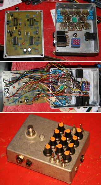
| P.S.: In case you may wonder - I omitted the second CV input and the Line/Mic switch, as I'm sure I'd never have used them. |
|
|
Back to top
|
|
|
gabbagabi
Joined: Nov 29, 2008
Posts: 652
Location: Berlin by n8
Audio files: 23
|
| Posted: Sun Dec 02, 2018 10:48 pm Post subject:
|
|
|
glad to hear u've fixed it  |
|
|
Back to top
|
|
|
|

 Forum index » DIY Hardware and Software » MusicFromOuterSpace.com designs by Ray Wilson