| Author |
Message |
voronin75
Joined: Jun 20, 2018
Posts: 6
Location: ukraine
|
 Posted: Sun May 26, 2019 7:53 am Post subject:
MFOS VCO - strange story with op amps Posted: Sun May 26, 2019 7:53 am Post subject:
MFOS VCO - strange story with op amps |
  |
|
Hello!
I have two MFOS SL Mini markII, one completed Ultimate and one Ultimate in which I connected only VCOI for the test.
I have a strange problem with VCO calibration tracking 1v/oct for all instruments.
Power 12V, clean.
Use U1 LF442, two match pair of 2n3904 (match by Ian Fritz method), U2 and U4 - TL072CP
In all cases there is a calibration problem - it is impossible to raise the frequency more than 740-760Hz when calibrating the range of 100-800 Hz using TL072 as comparator (U2 according to the VCO Ultinate scheme) Also when replaced with LF442. It is perfectly calibrated when installing the TL082 in a plastic case, but does not work when installing the TL082 in a ceramic case. What is it? It seems to lack current at the output of U2?
Where to look for the problem, maybe someone knows? Please HELP!
[/list]
Last edited by voronin75 on Thu May 30, 2019 12:53 am; edited 1 time in total |
|
|
Back to top
|
|
 |
voronin75
Joined: Jun 20, 2018
Posts: 6
Location: ukraine
|
| Posted: Sun May 26, 2019 10:49 pm Post subject:
|
|
|
| So. The problem was solved by replacing U2 (according to the ultimate scheme) tl072 by tl082 for all devices. Obviously there was not enough current at the u2 output. Could Ray have designed a circuit for op with greater sensitivity? Can someone explain? Calibrated ideally. One confuses - tl082 is somewhat noisier than tl072. |
|
|
Back to top
|
|
|
ixtern
Joined: Jun 25, 2018
Posts: 145
Location: Poland
|
| Posted: Sun May 26, 2019 10:57 pm Post subject:
|
|
|
| voronin75 wrote: | | So. The problem was solved by replacing U2 (according to the ultimate scheme) tl072 by tl082 for all devices. Obviously there was not enough current at the u2 output. Could Ray have designed a circuit for op with greater sensitivity? Can someone explain? Calibrated ideally. One confuses - tl082 is somewhat noisier than tl072. |
Maybe you have run into one of those false ICs?
Lately I have bought from local dealer some TL072CP (TI), TL074CN (TI) and OPA2134PA (BB) (together about 40 pieces). ALL of them were false: they have large input currents like low quality bipolar OpAmps (dozens of nA). |
|
|
Back to top
|
|
|
voronin75
Joined: Jun 20, 2018
Posts: 6
Location: ukraine
|
| Posted: Sun May 26, 2019 11:30 pm Post subject:
|
|
|
| Unlikely. Chips from different suppliers and bought at different times during the year. Another question is, why didn't lm394 not working instead the pair of 2n3904? At the output of 7 U1 is 9.5v ))) .... I don’t know, maybe all three chips are defective... And at the expense of tl072- I tried lf442- same result , not calibrated like72x. |
|
|
Back to top
|
|
|
voronin75
Joined: Jun 20, 2018
Posts: 6
Location: ukraine
|
| Posted: Fri May 31, 2019 2:50 am Post subject:
|
|
|
| Problem solved. In a strange way. There are two types of DIP chips, in particular the TL072: in a ceramic case and in a plastic case. If I correctly understood from TI data sheet, the ceramic element is cut on the meedle of front age (marking pin.1), a plastic extruded point near pin.1. TL072 in the ceramic package does not work correctly in the comparator section of MFOS VCO, but in other schemes work well. TL072 works correctly in a plastic case, TL082 also in a plastic case. I have reason to suspect that these chips are slightly different, because TL072 I bought at different times and from different suppliers, although the probability of defect probably exists. Perhaps the situation is similar to the one that described ixtern. And if you have some strange problem with VCO or calibration you can change the chip at first, or match from other analog. |
|
|
Back to top
|
|
|
ixtern
Joined: Jun 25, 2018
Posts: 145
Location: Poland
|
| Posted: Mon Jun 03, 2019 1:39 am Post subject:
|
|
|
| voronin75 wrote: | | Problem solved. In a strange way. There are two types of DIP chips, in particular the TL072: in a ceramic case and in a plastic case. If I correctly understood from TI data sheet, the ceramic element is cut on the meedle of front age (marking pin.1), a plastic extruded point near pin.1. TL072 in the ceramic package does not work correctly in the comparator section of MFOS VCO, but in other schemes work well. TL072 works correctly in a plastic case, TL082 also in a plastic case. I have reason to suspect that these chips are slightly different, because TL072 I bought at different times and from different suppliers, although the probability of defect probably exists. Perhaps the situation is similar to the one that described ixtern. And if you have some strange problem with VCO or calibration you can change the chip at first, or match from other analog. |
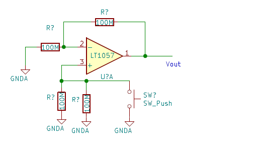
Try to check OpAmps with this simple tester. When switch is off, output voltage should be within few milivolts (or less). When switch is on (noninverting OpAmp input shortened to ground), output voltage will differ by the Ibias * 50 MOhm so 1 nA of input bias current should give 50mV output voltage.
Good TL072 should have bias current at normal temperature less than 0.2nA,
so max 10mV change on output.
In my case output voltage difference for fake ICs was about 100-200 mV what means 2-4 nA of input bias current what is rather characteristic for bipolar OpAmps.
If you don't have 100 MOhm resistors, you can chain 10-20 MOhms together.
High tolerance is not needed as we are interested in order of magnitude rather than exact value.
| Description: |
|
| Filesize: |
12.49 KB |
| Viewed: |
7463 Time(s) |
|
|
|
|
Back to top
|
|
|
voronin75
Joined: Jun 20, 2018
Posts: 6
Location: ukraine
|
| Posted: Mon Jun 03, 2019 2:33 am Post subject:
|
|
|
| Thank you! I will try. |
|
|
Back to top
|
|
|
|

 Forum index » DIY Hardware and Software » MusicFromOuterSpace.com designs by Ray Wilson
