| Author |
Message |
csj2k
Joined: Mar 10, 2019
Posts: 14
Location: UK
|
 Posted: Tue Jul 30, 2019 6:49 am Post subject:
4060 "Suboscilator" Stripboard & Olegtron Posted: Tue Jul 30, 2019 6:49 am Post subject:
4060 "Suboscilator" Stripboard & Olegtron |
  |
|
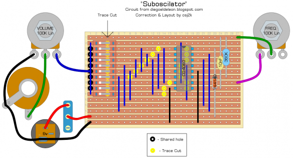
This is the first stripboard I've published. I've made it from this layout and it works but there's a chance the layout could be improved and I would welcome feedback. If I were to make this for regular use I would replace the DIP switches with toggle switches. I only made this circuit to better understand the Olegtron.
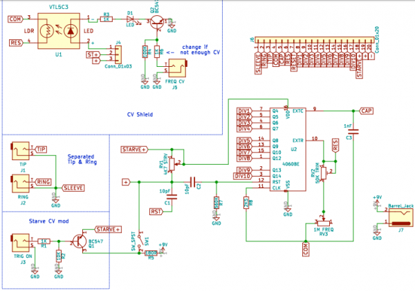
I printed the original diagram but can't find the file to publish and can't find it on the site which was referenced on the schematic. There was a simple error in that pin 12 was left floating instead of being connected to ground.
The DIP switches allow you to turn any of the 10 dividers on or off to make some very interesting sounds from punchy percussion to all out musical madness! I actually found the schematic after seeing the "Olegtron" which also uses the CD4060. "Baron von Pooppenstein" was kind enough to share his schematic for the Olegtron in the product's own forum (with Olli Suorlahti's permission) and I have permission from the Baron and Olli to share it here. While they were happy to share for us DIY'ers, it is only fair that I should provide a link to the product which I can whole-heartedly recommend - this thing is so simple but has huge potential and the thing I like most about it is that it's insane! They have also released a Eurorack version. https://www.olegtron.com/olegtron-4060
| Description: |
|
| Filesize: |
117.97 KB |
| Viewed: |
860 Time(s) |
| This image has been reduced to fit the page. Click on it to enlarge. |
|
| Description: |
|
| Filesize: |
109.96 KB |
| Viewed: |
743 Time(s) |
| This image has been reduced to fit the page. Click on it to enlarge. |
|
_________________
So many circuits, so little time
Last edited by csj2k on Tue Jul 30, 2019 2:01 pm; edited 1 time in total |
|
|
Back to top
|
|
 |
PHOBoS

Joined: Jan 14, 2010
Posts: 5881
Location: Moon Base
Audio files: 709
|
| Posted: Tue Jul 30, 2019 12:08 pm Post subject:
|
|
|
Just a word of caution, you shouldn't connect outputs directly together which is what you are doing now if
you turn more than one switch on. The correct way to do it would be to add diodes in series with the outputs.
Also I don't see a current limiting resistor for the LED, but you might be using one with it build in.
And then there is the diode + 1K resistor in parallel connected in series with pin 16 of the chip.
The 1K could be used for starving but is bypassed by the diode. Or was that 1K meant for the LED ?
The rest looks ok.
_________________
"My perf, it's full of holes!"
http://phobos.000space.com/
SoundCloud BandCamp MixCloud Stickney Synthyards Captain Collider Twitch YouTube |
|
|
Back to top
|
|
|
csj2k
Joined: Mar 10, 2019
Posts: 14
Location: UK
|
| Posted: Tue Jul 30, 2019 1:48 pm Post subject:
|
|
|
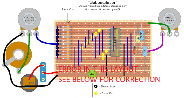
Thank you for looking it over PHOBoS. You're absolutely right about the 1K resistor - it was for the LED. I checked it over several times and was happy with it. When I came to make it from the layout, I made a last minute change to the position of the LED but after updating the DIYLC file I clearly didn't spend enough time checking the change. I'll fix it and post an amended one shortly.
The design (without the diodes) is how I found it. The Olegtron also allows you to use multiple dividers and there are no diodes involved there either. Is it potentially damaging without the diodes or is it just against accepted convention?
_________________
So many circuits, so little time |
|
|
Back to top
|
|
|
csj2k
Joined: Mar 10, 2019
Posts: 14
Location: UK
|
|
|
Back to top
|
|
|
PHOBoS
Joined: Jan 14, 2010
Posts: 5881
Location: Moon Base
Audio files: 709
|
| Posted: Tue Jul 30, 2019 4:16 pm Post subject:
|
|
|
| csj2k wrote: | | When I came to make it from the layout, I made a last minute change to the position of the LED but after updating the DIYLC file I clearly didn't spend enough time checking the change. |
I am familiar with those last minute changes. 
| Quote: | | Is it potentially damaging without the diodes or is it just against accepted convention? |
It can potentially fry the chip. Fried chips can be tasty but I wouldn't recommend taking a byte of a CMOS chip.
joking aside, if some outputs are high (V+) and some are low (GND) and they are connected together you are creating a dead short.
The 4060 will limit the current to some degree so it's not likely to damage whatever you use to power it with, but the chip doesn't
really have any protection and too much current can damage it (sometimes quite spectacularly). This is also why it's a good practise
to use resistors in series with the ouputs if you make them patchable.
btw if you use resistors or better potentiometers in series with the outputs and you connect them together you can create some nice waveforms.
_________________
"My perf, it's full of holes!"
http://phobos.000space.com/
SoundCloud BandCamp MixCloud Stickney Synthyards Captain Collider Twitch YouTube |
|
|
Back to top
|
|
|
csj2k
Joined: Mar 10, 2019
Posts: 14
Location: UK
|
| Posted: Sat Aug 10, 2019 9:59 am Post subject:
|
|
|
Thank you for the explanation, that makes sense.
_________________
So many circuits, so little time |
|
|
Back to top
|
|
|
|

 Forum index » DIY Hardware and Software » Musical Interfaces