| Author |
Message |
Dr. K
Joined: Jan 15, 2020
Posts: 52
Location: wisconsin
|
 Posted: Wed Feb 12, 2020 8:49 am Post subject:
4040 Divider circuit--some input requested Posted: Wed Feb 12, 2020 8:49 am Post subject:
4040 Divider circuit--some input requested |
  |
|
hello,
I got a couple of basic oscillator circuits built, now working on some gadgets to connect them through.
I have some 4040 divider ICs, and was hoping to build a circuit to add some lower octaves to the outputs of the oscillators, make it all switchable...
The circuits look straight forward--the osc. output goes to the clock of the 4040, and then you take whatever output you need, combining them through resistors.
My question is simply--how can I also mix in the primary frequency? I'd like to add the lower octaves to the original wave form. I'm thinking I could just split the input (the output of the drive oscillator) into 2, use one lead to drive the 4040, and the other to mix back in on the other side? What is a good way to do this? Thanks for any info on my newbie questions |
|
|
Back to top
|
|
 |
gabbagabi

Joined: Nov 29, 2008
Posts: 652
Location: Berlin by n8
Audio files: 23
|
|
|
Back to top
|
|
|
Dr. K
Joined: Jan 15, 2020
Posts: 52
Location: wisconsin
|
| Posted: Thu Feb 13, 2020 8:24 am Post subject:
|
|
|
Thanks for the info.
I bread boarded the circuit last night, using large resistors to tie the outputs of f/2, f/4, and f/8 together. I think it was a HackaDay post that recommended using ~100k.
The circuit works--but the 4040 outputs much, much quieter than the input frequency (if i tie that in to the output, without a resistor). Tonight, I need to find another solution. The input frequency is MUCH louder, and the lower harmonics can barely be detected.
I'm curious if I need to use resistors to tie them together, or if the outputs can jsut be tied together directly, thereby not diminishing the volume. Nic Collins' book doesn't mention using resistors. Worht a try I guess.
The idea is sound--I just need to sort out the balance issue in an easy way. I'll study your simulation more carefully when I get a moment. T hanks again!! |
|
|
Back to top
|
|
|
gabbagabi
Joined: Nov 29, 2008
Posts: 652
Location: Berlin by n8
Audio files: 23
|
| Posted: Thu Feb 13, 2020 8:40 am Post subject:
|
|
|
| may u could provide a link to the schemo uve used? |
|
|
Back to top
|
|
|
Dr. K
Joined: Jan 15, 2020
Posts: 52
Location: wisconsin
|
| Posted: Thu Feb 13, 2020 8:46 am Post subject:
|
|
|
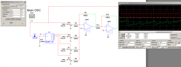
it was basically this : https://hackaday.com/2015/02/17/logic-noise-8-bits-of-glorious-sounds/
But notice from the schematic, their is no provision for tying in the original wave form. Just the lower octaves.
With the 100k resistors, if I split the input and tie half of it to the output (the lower octaves), the original wave form is much, much louder. If i put a resistor on the original wave form, then the entire signal is very quiet.
Their must be an elegant way to do this, without attenuating the signal so badly. I need to read up on it--do the output resistors actually need to be so large? 100k? Could I drop them to maybe 1k? Or, as I mentioned, couple the outputs through diodes? |
|
|
Back to top
|
|
|
Dr. K
Joined: Jan 15, 2020
Posts: 52
Location: wisconsin
|
| Posted: Thu Feb 13, 2020 8:58 am Post subject:
|
|
|
I think what I'm hoping to do is figure out how to mix the original wave form with the lower harmonics, using some kind of filter (just a first or second order RC filter) to round out the sharp edges a bit. Just to make the signal a bit more organic, and less cheezy computer game sounding.
I'm not sure exactly what proportions I would be mixing the signals in to get that effect. And I also realize that in real stringed instruments, the proportions change with time--initially it's exclusively the fundemental, that evolves in time. Still,the lower harmonics would add thickness and richness to the sound I think.
Forgive my questions--I'm trained as a chemist, and am a complete self-taught hack of an electrical engineer. Trying to learn. Actually reading specs, using an oscilloscope to try and figure out circuits... Just little in the way of formal training in the subject. |
|
|
Back to top
|
|
|
JovianPyx

Joined: Nov 20, 2007
Posts: 1988
Location: West Red Spot, Jupiter
Audio files: 224
|
| Posted: Thu Feb 13, 2020 9:06 am Post subject:
|
|
|
Never tie CMOS device outputs together. It can damage the chip.
_________________
FPGA, dsPIC and Fatman Synth Stuff
Time flies like a banana.
Fruit flies when you're having fun.
BTW, Do these genes make my ass look fat?
corruptio optimi pessima
|
|
|
Back to top
|
|
|
|

 Forum index » Instruments and Equipment » Modular Synthesis