| Author |
Message |
NuttyMonk
Joined: Jun 30, 2020
Posts: 63
Location: UK
|
|
|
Back to top
|
|
 |
NuttyMonk
Joined: Jun 30, 2020
Posts: 63
Location: UK
|
|
|
Back to top
|
|
|
NuttyMonk
Joined: Jun 30, 2020
Posts: 63
Location: UK
|
|
|
Back to top
|
|
|
NuttyMonk
Joined: Jun 30, 2020
Posts: 63
Location: UK
|
|
|
Back to top
|
|
|
NuttyMonk
Joined: Jun 30, 2020
Posts: 63
Location: UK
|
|
|
Back to top
|
|
|
NuttyMonk
Joined: Jun 30, 2020
Posts: 63
Location: UK
|
|
|
Back to top
|
|
|
dk
Joined: Feb 12, 2019
Posts: 115
Location: Europe
|
 Posted: Fri Sep 25, 2020 2:18 pm Post subject: Posted: Fri Sep 25, 2020 2:18 pm Post subject:
|
  |
|
Cool idea!
Will it not matter that your step length will throw your sequencer out of tempo?
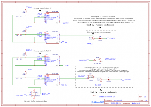
Referring to sheet 5 where you are using an AND with a 12V and 5V input: the logic gates need to see at least 1/2 their supply voltage to turn on, so if you power them with 12V and have one input only ever reach 5V, they won't work. You can either up the 5V to something higher or bring down the other 12V input and run them at 5V.
_________________
Horrors Of Dial-Up! on Facebook
Horrors Of Dial-Up! on Instagram |
|
|
Back to top
|
|
|
NuttyMonk
Joined: Jun 30, 2020
Posts: 63
Location: UK
|
| Posted: Fri Sep 25, 2020 2:37 pm Post subject:
|
|
|
Regarding the AND gate. I think I'll just use a 12v source for the 2nd input as well as the 12v mute input. I don't necessarily need to use 5V for the Pitch CV quantising, it could be higher, but it will make it harder to find a specific note using a potentiometer. I can just use a voltage divider to bring it down again. With 5V i can get 5 octaves which is probably more than enough. I can probably add in an octave rotary switch and add voltages in 1v steps if i want to go higher.
The point of the Clock CV is too be able to manually adjust step lengths for each step, but yes, now that i think about it there could be problems keeping it in time with another clock source. It also means that if i was using the sequencer clock for other elements in a song, they would also be triggering at the same unusual rhythms as the clock. I'm using an Arduino to get the BPM from the clock and i could use that to help me sync to another clock with a reset every 16 beats like Colin Benders did in his video.
I previously created an Arduino clock source and it might be easier to go back to that and modify it again. Coding the functionality into it to maintain a set BPM and still have the ability to adjust each step individually would certainly be easier and might produce a better result than what i currently have in the schematics.
Thanks for the input dk
Cheers
NM |
|
|
Back to top
|
|
|
dk
Joined: Feb 12, 2019
Posts: 115
Location: Europe
|
| Posted: Sat Sep 26, 2020 2:58 am Post subject:
|
|
|
No problem. I think manual selection of step length would make it easier to implement (you could have a 4017 for each step determine the step length, their outputs feeding your sequencer core), but putting that under CV control might make things so complex that going digital would be the way to go.
If manual step length is ok, considering checking this out: https://electro-music.com/forum/topic-27157.html&postorder=asc
_________________
Horrors Of Dial-Up! on Facebook
Horrors Of Dial-Up! on Instagram |
|
|
Back to top
|
|
|
NuttyMonk
Joined: Jun 30, 2020
Posts: 63
Location: UK
|
| Posted: Sat Sep 26, 2020 4:20 am Post subject:
|
|
|
That's looks and sounds really nice. I wouldn't know where to start with digital though. Still getting my head around the analog stuff.
Been working on code for the arduino clock source and it's coming along ok. Aiming for 2 clock outputs which are synced with one having cv controllable step adjustments of up to 50% of step length. That way i can get a normal clock and adjustable clock from the same source. and not worry about them getting out of time with each other. Will need an external ADC though for the 16 step-length CV inputs. Since i have a bunch of them lying around that should be fine. |
|
|
Back to top
|
|
|
dk
Joined: Feb 12, 2019
Posts: 115
Location: Europe
|
| Posted: Sun Sep 27, 2020 6:15 am Post subject:
|
|
|
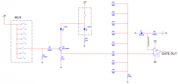
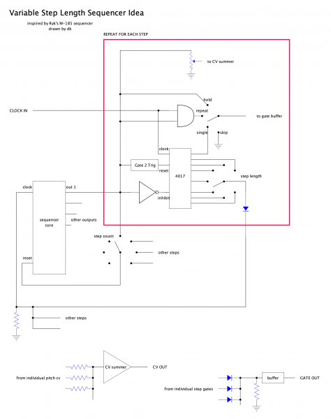
By "digital" I meant that it would be easier to code a CV adjustable step length that corresponds with the original clock in the Arduino than to try and implement it with logic chips, etc.
If it doesn't need to be CV controllable, here's where I would start. It's just a block diagram for brainstorming. The number of beats per step, the number of steps, etc., would be tailored to your needs. There are some bugs to work out, like the relationship between the inhibit and reset on the 4017 will probably need to be tweaked, there probably needs to be a gate to trigger after the step length switch, etc. You could opt for a simple sequencer core like a 4017, or something more complex ie CD4516 + CD4051's and it would still more or less work the same way.
| Description: |
|
| Filesize: |
185.14 KB |
| Viewed: |
219 Time(s) |
| This image has been reduced to fit the page. Click on it to enlarge. |
|
_________________
Horrors Of Dial-Up! on Facebook
Horrors Of Dial-Up! on Instagram |
|
|
Back to top
|
|
|
NuttyMonk
Joined: Jun 30, 2020
Posts: 63
Location: UK
|
| Posted: Sun Sep 27, 2020 8:35 am Post subject:
|
|
|
Ah, i see. This is like the clone you showed me in the link you posted, the M185 Roland clone. Now that i see it laid out like that, it makes sense. For some reason i'm having more fun working on sequencers than any other modules. I'll keep this in mind for when the current project is done.
I've pretty much worked out all the code for an Arduino clock core but i'm having problems with the mux input. Getting some random noise on the signal. It's a mess of cables with all 16 channels built up on a breadboard so i'm gonna switch to a Teensy 3.2. It has 21 analog inputs and runs at 72 MHz compared to the arduino at 16 MHz. Not that i really need the extra speed but it will be nice to get rid of the mux. I can use port mapping and simplify/speed up the reading of the pots. Lots less code, lots less mess.
Thanks for the schematic dk. It gives me lots of ideas. I'll keep it in my collection for now.
Cheers
NM
p.s. i ordered a Sainsmart 3018 Prover CNC milling/routing machine so making my own PCB's will be possible when it arrives. Looking forward to that learning curve. Just hope my neighbours don't mind the noise. Gonna put it in my cupboard and line it with studio quality soundproofing and a webcam to monitor it when it's in use. My bedroom is more like a workshop than a bedroom now. Lol |
|
|
Back to top
|
|
|
gabbagabi

Joined: Nov 29, 2008
Posts: 652
Location: Berlin by n8
Audio files: 23
|
|
|
Back to top
|
|
|
NuttyMonk
Joined: Jun 30, 2020
Posts: 63
Location: UK
|
|
|
Back to top
|
|
|
dk
Joined: Feb 12, 2019
Posts: 115
Location: Europe
|
| Posted: Sat Oct 03, 2020 1:57 pm Post subject:
|
|
|
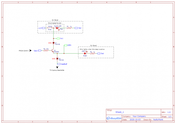
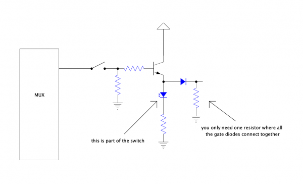
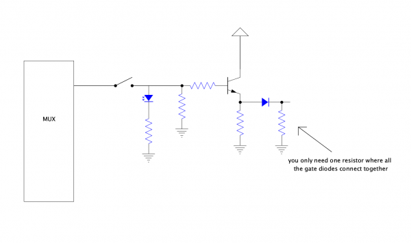
I don't think you need the top diode at all. The output of the transistor looks fine, assuming there will be a pull up/pull down resistor where the bottom diode connects to the gate bus.
As for the switch, I would have expected it to cut off signal to the base of the transistor, not voltage to the collector. It might have unexpected behavior that way. Someone else with more knowledge than I could probably fill you in, but in the mean time, try it and see if it works?
_________________
Horrors Of Dial-Up! on Facebook
Horrors Of Dial-Up! on Instagram |
|
|
Back to top
|
|
|
NuttyMonk
Joined: Jun 30, 2020
Posts: 63
Location: UK
|
|
|
Back to top
|
|
|
NuttyMonk
Joined: Jun 30, 2020
Posts: 63
Location: UK
|
| Posted: Sun Oct 04, 2020 9:41 am Post subject:
|
|
|
| Actually, now i've had a chance to test it again, that setup doesn't work. When the switch is on and the cd4514 is set to LOW (meaning that the sequencer is on a different step from the current one), i still get a decent voltage out of the transistor. Damn, these things are complicated. |
|
|
Back to top
|
|
|
gabbagabi
Joined: Nov 29, 2008
Posts: 652
Location: Berlin by n8
Audio files: 23
|
|
|
Back to top
|
|
|
NuttyMonk
Joined: Jun 30, 2020
Posts: 63
Location: UK
|
| Posted: Mon Oct 05, 2020 9:22 am Post subject:
|
|
|
| I think i have a good work-around now. I'm using an op-amp as a comparator. There's enough of a difference between a HIGH and LOW signal that i can compare them and get a nice clean HIGH and LOW signal out of the comparator to send on to the individual rows AND gates. Still a wee bit of testing to go, then i hope this bloody Gate row will be done. lol |
|
|
Back to top
|
|
|
NuttyMonk
Joined: Jun 30, 2020
Posts: 63
Location: UK
|
| Posted: Mon Oct 05, 2020 10:03 am Post subject:
|
|
|
I'll have a wee test of that setup when i have some time gabbagabi. Thanks for your input.
Cheers
NM |
|
|
Back to top
|
|
|
dk
Joined: Feb 12, 2019
Posts: 115
Location: Europe
|
|
|
Back to top
|
|
|
NuttyMonk
Joined: Jun 30, 2020
Posts: 63
Location: UK
|
| Posted: Tue Oct 06, 2020 9:03 am Post subject:
|
|
|
Thanks dk.
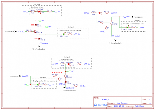
The LED in the switch goes on or off when the switch is on or off. The other LED only goes on when that step is active. As the switch with the LED will be panel mounted, i wanted to minimise the number of connections from the switch and LED's back to the main PCB behind.
The setup i have now works on the breadboard (with a 4-step setup) although i've only just ordered the illuminated switch itself (will be here in a day or two). The comparator is what really makes it all work well and give a clean 12V(ish) output to head off to the separate rows AND gates. I've never designed a comparator setup before and was surprised how easy it was.
I'll post the single gate schematic and comparator in a bit when i have some time. In the meantime i'm trying to finish soundproofing my cupboard to get my CNC milling machine up and running. Just ordered a USB3 hub and cables so i can watch it work on a webcam while the doors are closed. 
Cheers
NM |
|
|
Back to top
|
|
|
dk
Joined: Feb 12, 2019
Posts: 115
Location: Europe
|
|
|
Back to top
|
|
|
NuttyMonk
Joined: Jun 30, 2020
Posts: 63
Location: UK
|
| Posted: Mon Oct 19, 2020 4:02 pm Post subject:
|
|
|
Finally got round to updating the Schematic and getting it ready for you guys to see. Been working on the CNC milling machine since it arrived.
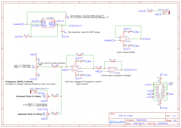
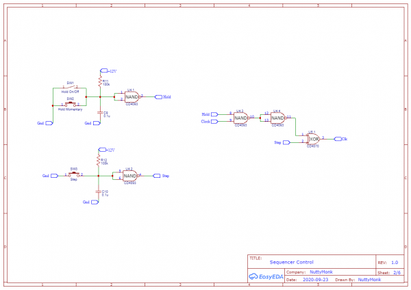
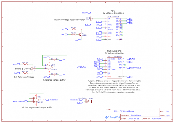
The design has changed again. I went through all of the Logic IC's on RS Components and whittled down a list quite quickly. They had to be cheap, useful (meaning they had 16 channels), and easy to work with and easy to get, so i settled on the CD4029 and CD4067. The only difference is that you can't get the CD4067 easily or cheaply in DIP format any more so i decided to use the surface mount SOIC versions of both of those chips to save space on the PCBs and make it easier to work with when designing the PCB. Keeping a component completely on just one side of the PCB is easier when it comes to routing. Using SMD resistors too. I also got used to using ground planes and that simplified things even more. So here is the schematic. You can ignore all of the headers dotted about. They are for the PCB design. The schematic is simpler i think than the last one.
I think i have all of the CMOS stuff designed OK as well as the CV rows and the Pitch row. The Teensy code is almost done, just trying to simplify and speed it up, not that it really needs speeded up, seems accurate and stable enough as it is but i'd rather get it as good as i can.
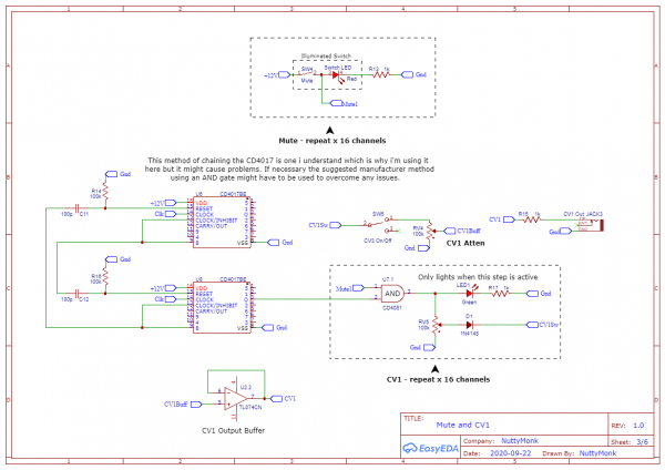
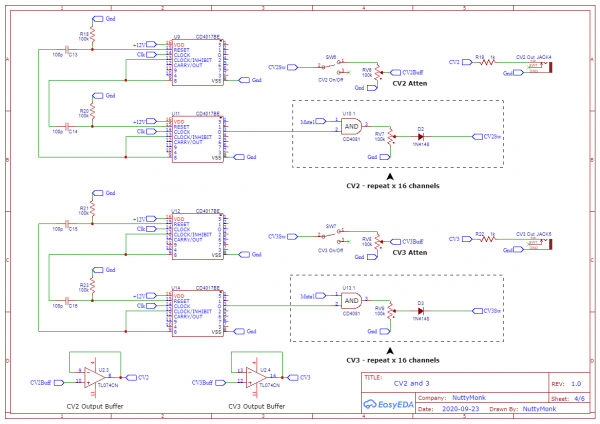
The stuff i am most concerned about is the Gate row (again) and making sure i get all of the LED current limiting resistors values correct. I've gated the input voltage to the 4067s which makes things easier i think, even though i needed to attenuate the voltage for the Pitch row down to 5V. I'm using a trim pot for that.
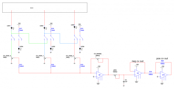
Any advice on the CMOS drop-down resistors setup (if i've missed anything or gotten anything wrong) would be a help. And any general comments would also be useful. I'm sure i'll lose some voltage after the gate row switches and LEDs but as long as it's above 6V, the AND gate will work OK.
I've actually yet to breadboard any of this since the amount of breadboard space i have isn't enough and i don't have a bazillion pots lying around unused but one step at a time. Buying pots and the CD4029 CD4067 IC's will be the next purchases i reckon. I just have enough space on my CNC milling machine that the preliminary PCB design i've done can be milled OK.
Thanks in advance,
Cheers
NM
| Description: |
|

Download (listen) |
| Filename: |
NuttyMonk_Schematic_4029 4067 Sequencer_2020-10-19_23-57-31.pdf |
| Filesize: |
785.46 KB |
| Downloaded: |
150 Time(s) |
|
|
|
Back to top
|
|
|
dk
Joined: Feb 12, 2019
Posts: 115
Location: Europe
|
| Posted: Tue Oct 20, 2020 5:04 am Post subject:
|
|
|
Mostly looking good!
There are some things that are unnecessary but probably proper (having the up/down switch connect to ground when there is already a pulldown resistor after the switch) and I'm not sure why you would want center detent pots on a unipolar CV, unless you have the Arduino programmed so that 2.5V means no change in CV? Just note that some center detent pots have a tolerance where the dentent is, meaning you might need to program a "dead zone" around 2.5V to keep from having slight differences in step length.
There are also a few things that seem like an odd workaround - namely using and AND gate to square up the All Gates and then an opamp buffer afterwards. You'd need less parts if you just ditch the 4081 and make the opamp a comparator instead of a buffer. Unless you meant to AND the All Gates signal with the Clock instead of 12V, so that you'd get a proper pulse out of each step?  
For the CV summing, I think you'd be better off using summing resistors instead of diodes. The diodes will make the first part of the pot rotation non-responsive, as nothing under 0.6-0.7V will make it through the diode (most of the whole first octave of range in a 1V/Octave system!). I'd use 100K summing resistors and make the resistor in the feedback loop of the summing amp switchable if you want to be able to change the CV range. Out of curiosity, why have the attenuator at the end if you're also going to be switching the gain of the summing amp? Wouldn't it be easier to just have a switch that lets you choose presets (3V, 5V, 12V, etc) and a pot (for variable range)?
And the purpose of the on/off switch is....? (understandable for gates, but not sure what you'd use it for on a CV out?)
As a side note, I also have a limited capacity to breadboard, so I built out only the first 4 steps of my sequencer as a sort of "proof of concept" to make sure it would work as expected. Even if you test individual sections of each step (only build out the gates, or one of the CV sections, etc), it could prevent you from etching boards that you end up needing to do lots of mods to
_________________
Horrors Of Dial-Up! on Facebook
Horrors Of Dial-Up! on Instagram |
|
|
Back to top
|
|
|
|

 Forum index » DIY Hardware and Software