| Author |
Message |
dslamnig
Joined: Dec 18, 2020
Posts: 28
Location: Zagreb, Croatia
Audio files: 6
|
 Posted: Thu Feb 04, 2021 4:06 pm Post subject:
Dual-core VCO project Posted: Thu Feb 04, 2021 4:06 pm Post subject:
Dual-core VCO project
Subject description: Designing and building a dual-core VCO |
  |
|
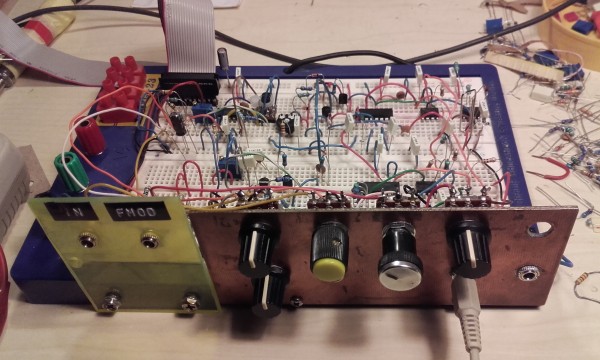
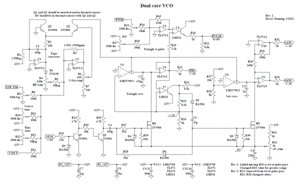
This is my first VCO design, I thought I'd share it with the group hoping for comments, suggestions, advice. It's still on the breadboard, there's still time to change it for the better.
I've started out with the Triangular/Square-Wave VCO example in the LM13700 datasheet (https://www.ti.com/lit/ds/symlink/lm13700.pdf), thinking about making a simple LFO. But the project kept creeping all over my breadboard, turning into a full-fledged VCO, dual-core at that. Now I'm running out of connector wires which is a sure sign of maximum circuit complexity - time to wrap it up.
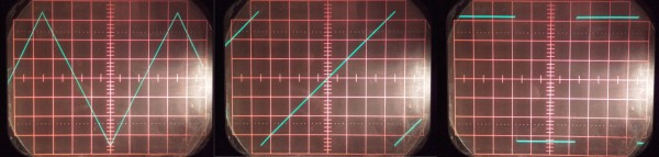
I've tried to keep things as simple as possible, cutting as many corners as I could while maintaining good waveforms. In the end it's not as simple as I'd like it to be, but I did manage to keep it down to 2 OTAs, 2 comparators, 6 opamps, 2 FETs and 4 BJTs. For that you get triangle, variable pulse and rising and falling ramps (because I'll be using it as a LFO, too, and there's no way to get deep space proximity alert alarms right without both). Also there's hard sync on all waveforms. The frequency range is about 0.1Hz to 25kHz, good enough for my old ears.
Triangle core
The triangle core is classic, with the LM311 comparator as the polarity switcher. I didn't want the slew rate of an opamp here, and I especially didn't want to fiddle with a discrete BJT Schmitt-trigger. LM311 is pretty mediocre as comparators go, but it has an open emitter output which proved to be very useful.
Saw core
Tri core up and running, I tried out a couple of tri-to-saw conversion methods and was not satisfied with results. There's always a connection glitch in the middle, and the slope of the jump from one to the other polarity is so-so. So I added a saw core which is slaved to the tri core. It's just a cap charged by an OTA and discharged by a FET on every tri cycle.
Since the discharge has a more-or-less constant duration, there is some drop in saw peak-to-peak voltage at high frequencies, >10kHz. The same thing causes "normal" saw cores to go flat at high freq. But since the master core is triangle, this VCO has very good tracking - with some saw amplitude loss as a tradeoff.
Triangle-to-pulse
The tri-to-pulse circuit also uses the LM311 which despite mediocrity does better switching than an open-loop opamp. The pulses are 0V to +8V, IMO better for LFO triggering and sync than zero-centered pulses. The open emitter output allows it to go down to absolute zero, would not be possible with collector output.
Sync
It took me a long time to get the sync part right. For some convoluted reasons I'll not go into here it's not enough to sync only the tri core - the saw also has to get some. But the result is great fat hard saw sync. The synced pulse also sounds great, but it can be hard on the triangle. Tri would benefit from some type of soft sync, but as I said I ran out of wires.
Expo converter
The expo converter is lifted from Tom Henry's VCO-555 (https://electro-music.com/forum/topic-54623.html), with some minor resistor value mods to account for the +/-12V supply and the fact that it was feeding two OTAs in parallel, so I needed more juice. Also, I'm using a 1.87k +3300ppm tempco resistor instead of 2k +3500 in VCO-555. This is a great circuit that worked perfectly right off the bat, all due credit and respect goes to the author.
Please take a peek at the schematic and give me your thoughts.
Rev 1: Added missing R43 to tri-to-pulse part.
Changed R18 value for greater range.
Rev 2: R21 removed from tri-to-pulse part.
R13, R28 changed values.
Schematic updated.
| Description: |
|
| Filesize: |
140.36 KB |
| Viewed: |
909 Time(s) |
| This image has been reduced to fit the page. Click on it to enlarge. |
|
Last edited by dslamnig on Wed Mar 10, 2021 7:17 am; edited 6 times in total |
|
|
Back to top
|
|
 |
dslamnig
Joined: Dec 18, 2020
Posts: 28
Location: Zagreb, Croatia
Audio files: 6
|
|
|
Back to top
|
|
|
dslamnig
Joined: Dec 18, 2020
Posts: 28
Location: Zagreb, Croatia
Audio files: 6
|
|
|
Back to top
|
|
|
dslamnig
Joined: Dec 18, 2020
Posts: 28
Location: Zagreb, Croatia
Audio files: 6
|
| Posted: Wed Feb 10, 2021 2:38 pm Post subject:
Rev 1. |
|
|
Rev 1: Added missing R43 to tri-to-pulse part.
Changed R18 value for greater range.
Updated schematic in original post.
Last edited by dslamnig on Wed Feb 24, 2021 2:50 pm; edited 1 time in total |
|
|
Back to top
|
|
|
dslamnig
Joined: Dec 18, 2020
Posts: 28
Location: Zagreb, Croatia
Audio files: 6
|
|
|
Back to top
|
|
|
dslamnig
Joined: Dec 18, 2020
Posts: 28
Location: Zagreb, Croatia
Audio files: 6
|
| Posted: Wed Feb 24, 2021 2:56 pm Post subject:
Introduction |
|
|
I'm starting to feel a bit solipsistic here, so let me introduce myself:
I'm Davor Slamnig, but everybody except my wife and mother-in-law calls me Slama. I live in Zagreb, Croatia, and got my first soldering iron when I was seven. I have been wielding it amateurishly ever since, without much regard for theory, breaking Kirchoff's, Ohm's and other laws, always jumping over currents instead of using Wien bridges.
I got the modular bug a couple of years ago. Although I'm building all the modules myself, I decided to adhere to the Doepfer Eurorack standard. I've already built a VCO around the 3340 chip, and I set out to design one on my own. A few months ago I bought my first LM13700 and started playing with it. The result exceeded my wildest expectations - a perfectly usable dual-core VCO with a mean saw.
The components are pretty much run-of-the-mill, I've been able to get everything in local shops except the tempco resistor which I ordered from Germany. But an ordinary 2k resistor worked fine while I was developing the circuit.
Now I just have to make the panel and add some shielding, and it's ready to rock. I'll post some audio samples then.
Last edited by dslamnig on Sat Feb 27, 2021 11:26 am; edited 1 time in total |
|
|
Back to top
|
|
|
blue hell
Site Admin

Joined: Apr 03, 2004
Posts: 24678
Location: The Netherlands, Enschede
Audio files: 330
G2 patch files: 320
|
| Posted: Wed Feb 24, 2021 3:22 pm Post subject:
|
|
|
solipsistic ... oh dear ... we can't have that ... hi Slama 
Looks like you are building a nice VCO there .. and re. things getting sharper .. the scope pics don't look bad from here?
_________________
Jan
also .. could someone please turn down the thermostat a bit.

9 3 4 .. erm .. not 13 then? .. hmm, ah eight! .. yeah yeah as in 8647 .. 47 is an 88 .. pwew .. numbles! |
|
|
Back to top
|
|
|
dslamnig
Joined: Dec 18, 2020
Posts: 28
Location: Zagreb, Croatia
Audio files: 6
|
| Posted: Wed Feb 24, 2021 3:46 pm Post subject:
|
|
|
| Blue Hell wrote: | solipsistic ... oh dear ... we can't have that ... hi Slama
Looks like you are building a nice VCO there .. and re. things getting sharper .. the scope pics don't look bad from here? |
Hi BH! Yeah, the 1kHz breadboard waveforms don't look bad, but things got worse above 6kHz or so. Now it stays sharp above 10kHz - haven't really tested at this stage, will do when mounted on panel. |
|
|
Back to top
|
|
|
gabbagabi

Joined: Nov 29, 2008
Posts: 652
Location: Berlin by n8
Audio files: 23
|
| Posted: Fri Feb 26, 2021 8:33 am Post subject:
|
|
|
always good to see people designing!
big respect for to board-work!
iam a bit confused about the powerlanes, is it point or stripboard?
any chance to see the solderside?
one question: why it is good to have the open emitter on the LM311? I generally dont like them, i always wish those comparators could be more like "normal" opamps - just faster
cheers,gg |
|
|
Back to top
|
|
|
dslamnig
Joined: Dec 18, 2020
Posts: 28
Location: Zagreb, Croatia
Audio files: 6
|
| Posted: Fri Feb 26, 2021 11:41 am Post subject:
|
|
|
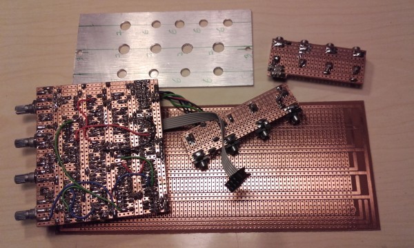
| gabbagabi wrote: | iam a bit confused about the powerlanes, is it point or stripboard?
any chance to see the solderside?
one question: why it is good to have the open emitter on the LM311? I generally dont like them, i always wish those comparators could be more like "normal" opamps - just faster |
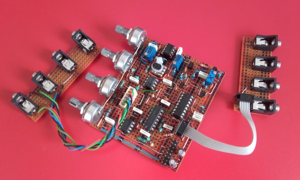
It's neither, it's a "joint hole" board. I bought a cheap stash of these on ebay, the layout is similar to a breadboard. I'm making one-off prototypes, no plans of going into mass production  I spend a night or two figuring out the topological problems, another night double-checking, and 2-3 nights for actual soldering... There's no rushing this, but I'm in no hurry. Backside photo attached - not so nice as the component side, but works ok. Also note the panel in the making. I spend a night or two figuring out the topological problems, another night double-checking, and 2-3 nights for actual soldering... There's no rushing this, but I'm in no hurry. Backside photo attached - not so nice as the component side, but works ok. Also note the panel in the making.
Regarding comparators, I'm a total newbie, this was the first time I've used them. But the force seems to be with me on this project
In the tri-to-pulse part I'm using the emitter output so the waveform can go down to zero volts. If I'd used the collector output there'd be a positive offset, few tens of millivolts. In the tri core I devised a trick to get +4/-4V output out of the comparator. Note the 5k and two 8.1k resistors, one bridged with a diode, and the emitter connected to -12V, not ground... I don't know if it's original, but IMHO it's neat.
| Description: |
|
| Filesize: |
1.84 MB |
| Viewed: |
532 Time(s) |
| This image has been reduced to fit the page. Click on it to enlarge. |
|
|
|
|
Back to top
|
|
|
electrotech

Joined: Apr 24, 2013
Posts: 47
Location: Ayrshire Scotland
|
| Posted: Sat Feb 27, 2021 2:52 am Post subject:
|
|
|
Hi Slama,
This is very impressive, especially the fact that it's your first VCO design !
The waveforms from the 'scope screen-shots look excellent too.
Well done.
Andy |
|
|
Back to top
|
|
|
dslamnig
Joined: Dec 18, 2020
Posts: 28
Location: Zagreb, Croatia
Audio files: 6
|
| Posted: Mon Mar 01, 2021 3:26 pm Post subject:
|
|
|
| electrotech wrote: |
This is very impressive, especially the fact that it's your first VCO design !
The waveforms from the 'scope screen-shots look excellent too.
|
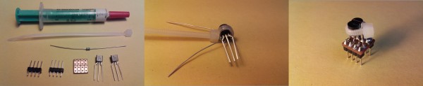
Thanks. The soldered version seems to track fine over at least 6 octaves (enough for my musical expression requirements), thanks to a good tempco, matched transistors and thermal paste. It's comparable to my 3340 VCO, will test some more.
The frequency range is 0.1Hz to 38kHz. The waveforms hold up pretty well at higher frequencies, especially triangle. Pulse is a bit disappointing geometrically, the down slope gets bent, but sounds nice and fat I think I may have botched something in the tri-to-pulse part...
I also measured power consumption, it draws 26mA/+12V and 25mA/-12V. Pretty green as VCOs go. |
|
|
Back to top
|
|
|
dslamnig
Joined: Dec 18, 2020
Posts: 28
Location: Zagreb, Croatia
Audio files: 6
|
| Posted: Tue Mar 02, 2021 12:54 pm Post subject:
|
|
|
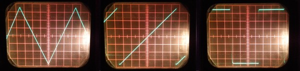
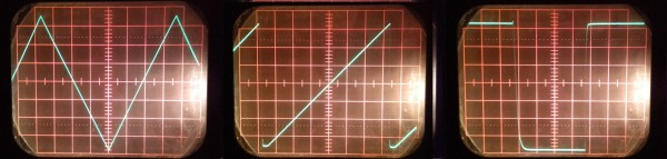
4kHz and 10kHz waveforms. Saw is starting to show the cap discharge time, pulse down-slope starts to bend, but triangle stays true.
| Description: |
|
| Filesize: |
1.38 MB |
| Viewed: |
313 Time(s) |
| This image has been reduced to fit the page. Click on it to enlarge. |
|
| Description: |
|
| Filesize: |
1.41 MB |
| Viewed: |
323 Time(s) |
| This image has been reduced to fit the page. Click on it to enlarge. |
|
|
|
|
Back to top
|
|
|
gabbagabi
Joined: Nov 29, 2008
Posts: 652
Location: Berlin by n8
Audio files: 23
|
| Posted: Thu Mar 04, 2021 8:53 am Post subject:
|
|
|
It's neither, it's a "joint hole" board. 
Yeah i ordered them myself but they where never delivered.
Afterwards i felt kind of lucky about, they are looking as if they would be full of phenol and other fancy chemicals 
But you are still alive and kicking, it seems it is not to bad?
Those little imperfections in the waveform makes your vco sounding different from the others. this is something good! And 6 octaves = wow! |
|
|
Back to top
|
|
|
AlanP
Joined: Mar 11, 2014
Posts: 746
Location: New Zealand
Audio files: 41
|
| Posted: Fri Mar 05, 2021 8:00 am Post subject:
|
|
|
| I'm really impressed by this -- both the circuit itself, and what I'm seeing of it's performance, and also the physical construction, which seems very well thought-out. |
|
|
Back to top
|
|
|
dslamnig
Joined: Dec 18, 2020
Posts: 28
Location: Zagreb, Croatia
Audio files: 6
|
| Posted: Fri Mar 05, 2021 12:02 pm Post subject:
|
|
|
| gabbagabi wrote: | It's neither, it's a "joint hole" board.
Yeah i ordered them myself but they where never delivered.
Afterwards i felt kind of lucky about, they are looking as if they would be full of phenol and other fancy chemicals
But you are still alive and kicking, it seems it is not to bad?
|
As I said, I've been inhaling soldering fumes since the age of 7, no signs of phenolic poisoning yet. I even have two healthy children, no genetic defects |
|
|
Back to top
|
|
|
dslamnig
Joined: Dec 18, 2020
Posts: 28
Location: Zagreb, Croatia
Audio files: 6
|
|
|
Back to top
|
|
|
dslamnig
Joined: Dec 18, 2020
Posts: 28
Location: Zagreb, Croatia
Audio files: 6
|
|
|
Back to top
|
|
|
dslamnig
Joined: Dec 18, 2020
Posts: 28
Location: Zagreb, Croatia
Audio files: 6
|
|
|
Back to top
|
|
|
dslamnig
Joined: Dec 18, 2020
Posts: 28
Location: Zagreb, Croatia
Audio files: 6
|
| Posted: Wed Mar 10, 2021 6:48 am Post subject:
|
|
|
And here's a saw bass line, PWM melody and a Jan Hammer wannabe triangle solo. My 3320 Pro-One clone filter and 3360 VCA are in the patch, with some reverb and delay added.
| Description: |
|

Download (listen) |
| Filename: |
Triangle lead.wav |
| Filesize: |
7.52 MB |
| Downloaded: |
493 Time(s) |
| Description: |
|
Download (listen) |
| Filename: |
Saw bass.wav |
| Filesize: |
3.08 MB |
| Downloaded: |
470 Time(s) |
| Description: |
|
Download (listen) |
| Filename: |
PWM lead.wav |
| Filesize: |
6.58 MB |
| Downloaded: |
514 Time(s) |
|
|
|
Back to top
|
|
|
dslamnig
Joined: Dec 18, 2020
Posts: 28
Location: Zagreb, Croatia
Audio files: 6
|
| Posted: Wed Mar 10, 2021 7:19 am Post subject:
Rev. 2 |
|
|
Rev 2 - as built:
R21 removed from tri-to-pulse part.
R13, R28 changed values.
Original schematic updated. |
|
|
Back to top
|
|
|
|

 Forum index » DIY Hardware and Software » Developers' Corner