| Author |
Message |
cyclic

Joined: Mar 15, 2015
Posts: 95
Location: hobart
|
 Posted: Thu Dec 19, 2019 6:44 pm Post subject: Posted: Thu Dec 19, 2019 6:44 pm Post subject:
|
  |
|
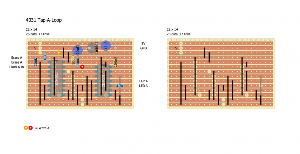
yep, I'm pretty sure I got it then!
If I have time to PCBify something for the original tap-looper I'll
- check here with schematics etc so its checked over
- make sure I make it small enough to either get 2 on a 10x7 or make it fairly easy to chain them together.
I don;t think I'll be doing that 63step cv sequencer even though I understand it now and reckon its a pretty inspired idea, but by doing the above it should make it easier to use anything I do for it. |
|
|
Back to top
|
|
 |
dadinfinitum
Joined: Dec 16, 2019
Posts: 41
Location: Maryland, US
|
| Posted: Sun Sep 13, 2020 7:29 am Post subject:
|
|
|
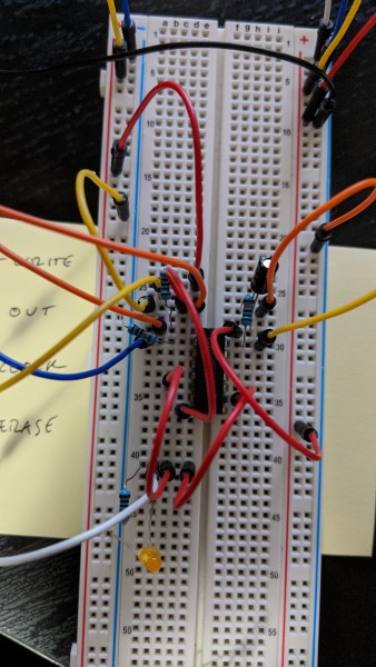
| I have tried to get both PHOBoS's simpler version and this version, but I can't get either of them to work. I've double and triple checked my circuit on the breadboard! |
|
|
Back to top
|
|
|
dk
Joined: Feb 12, 2019
Posts: 115
Location: Europe
|
| Posted: Sun Sep 13, 2020 7:49 am Post subject:
|
|
|
How are you testing it? Do you have a LED strapped across the output to see what's coming out?
It's a 64 step sequence, so if you use a slow clock, and can take a while for the chip to spit out what you've input.
_________________
Horrors Of Dial-Up! on Facebook
Horrors Of Dial-Up! on Instagram |
|
|
Back to top
|
|
|
dadinfinitum
Joined: Dec 16, 2019
Posts: 41
Location: Maryland, US
|
| Posted: Sun Sep 13, 2020 9:02 am Post subject:
|
|
|
| dk wrote: | How are you testing it? Do you have a LED strapped across the output to see what's coming out?
It's a 64 step sequence, so if you use a slow clock, and can take a while for the chip to spit out what you've input. |
I have the output as a gate for a 40106 osc. Also using a 40106 osc (albeit a slower one) for the clock. I have LEDs on both of those. Also using a multimeter on both the data in and the data out. |
|
|
Back to top
|
|
|
dk
Joined: Feb 12, 2019
Posts: 115
Location: Europe
|
|
|
Back to top
|
|
|
dadinfinitum
Joined: Dec 16, 2019
Posts: 41
Location: Maryland, US
|
| Posted: Wed Sep 16, 2020 5:06 am Post subject:
|
|
|
| Yeah, it seemed pretty simple, which is why I've been surprised it hasn't worked. I'll see if I can emulate your stripboard. |
|
|
Back to top
|
|
|
dadinfinitum
Joined: Dec 16, 2019
Posts: 41
Location: Maryland, US
|
| Posted: Wed Sep 16, 2020 7:09 am Post subject:
|
|
|
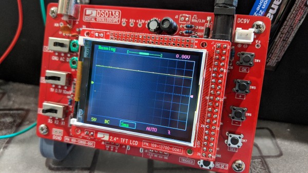
So, still no luck. The LED at the end doesn't light up, and the oscillator that is using the output as a gate doesn't activate. Using my scope on the output, it looks constantly high? Which is really weird.
| Description: |
|
| Filesize: |
3.1 MB |
| Viewed: |
542 Time(s) |
| This image has been reduced to fit the page. Click on it to enlarge. |
|
| Description: |
|
| Filesize: |
2.54 MB |
| Viewed: |
519 Time(s) |
| This image has been reduced to fit the page. Click on it to enlarge. |
|
|
|
|
Back to top
|
|
|
dk
Joined: Feb 12, 2019
Posts: 115
Location: Europe
|
| Posted: Wed Sep 16, 2020 7:27 am Post subject:
|
|
|
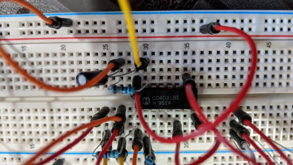
Hard to tell from the pic, but it looks like you haven't grounded the chip? Pin 8 should go to ground, while pin6 should connect with pin 10 and your output..
EDIT: I was under the impression that between pins 6 and 8 there was a loop, but that's probably just the picture cutting it that way.
_________________
Horrors Of Dial-Up! on Facebook
Horrors Of Dial-Up! on Instagram |
|
|
Back to top
|
|
|
dadinfinitum
Joined: Dec 16, 2019
Posts: 41
Location: Maryland, US
|
|
|
Back to top
|
|
|
PHOBoS

Joined: Jan 14, 2010
Posts: 5971
Location: Moon Base
Audio files: 709
|
| Posted: Wed Sep 16, 2020 11:07 am Post subject:
|
|
|
From what I can tell that looks ok.
You could try the bare minimum to see if the chip does anything at all:
pin1: GND
pin2: fast (KHz) oscillator input
pin3: NC
pin4: NC
pin5: NC
pin6: output
pin7: NC
pin8: GND
pin9: NC
pin10: GND
pin11: NC
pin12: NC
pin13: NC
pin14: NC
pin15: slow oscillator input
pin16: V+
If the CLK (2) frequency is fast enough the output (6) should pretty much follow the oscillator on the input (15).
Also move the chip to another part of the breadboard.
_________________
"My perf, it's full of holes!"
http://phobos.000space.com/
SoundCloud BandCamp MixCloud Stickney Synthyards Captain Collider Twitch YouTube |
|
|
Back to top
|
|
|
dadinfinitum
Joined: Dec 16, 2019
Posts: 41
Location: Maryland, US
|
| Posted: Wed Sep 16, 2020 5:41 pm Post subject:
|
|
|
| Good news: it works. Now to figure out what's wrong with the circuit. I even read through the datasheet and the CMOS cookbook to try and troubleshoot/test other configurations. |
|
|
Back to top
|
|
|
dadinfinitum
Joined: Dec 16, 2019
Posts: 41
Location: Maryland, US
|
| Posted: Thu Sep 17, 2020 12:46 pm Post subject:
|
|
|
I got the circuit to work!
The only issue: it starts high, so I have to hold erase through a cycle to clear it. I tried pulldowns on the write and erase switches, but nothing. Thoughts on that? |
|
|
Back to top
|
|
|
PHOBoS
Joined: Jan 14, 2010
Posts: 5971
Location: Moon Base
Audio files: 709
|
|
|
Back to top
|
|
|
dadinfinitum
Joined: Dec 16, 2019
Posts: 41
Location: Maryland, US
|
| Posted: Thu Sep 17, 2020 4:06 pm Post subject:
|
|
|
| If an easy solution is just "start in erase mode," then that's fine. (I'm using a traditional toggle switch for erase, and a keyboard switch for tapping) |
|
|
Back to top
|
|
|
dk
Joined: Feb 12, 2019
Posts: 115
Location: Europe
|
| Posted: Sat Sep 19, 2020 5:23 am Post subject:
|
|
|
Glad to see you got it working! I have two in my rig, one of which starts up empty, the other full. It's a bother, but not enough for me to fix it 
_________________
Horrors Of Dial-Up! on Facebook
Horrors Of Dial-Up! on Instagram |
|
|
Back to top
|
|
|
zaphod betamax
Joined: Nov 27, 2020
Posts: 62
Location: sarnia
|
| Posted: Fri Nov 27, 2020 8:32 am Post subject:
|
|
|
Don't forget about the CD4517.
Available at digikey.ca and other places |
|
|
Back to top
|
|
|
Estebandito
Joined: Dec 25, 2017
Posts: 33
Location: Amsterdam
Audio files: 3
|
| Posted: Sun Dec 20, 2020 5:38 am Post subject:
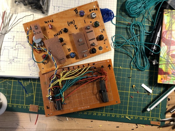
Just wanted to share my version of the tap looper |
|
|
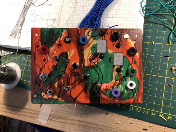
My version of the tap looper. It is pretty much the most basic version, with an external clock input as well as an inbuilt clock (with cap switch, and pulse/gate switch). Outputs are Q, inverted Q. Also there are two outputs from the 7-segment display drivers and one where I send those outputs through a NAND gate.
| Description: |
|
| Filesize: |
3.22 MB |
| Viewed: |
294 Time(s) |
| This image has been reduced to fit the page. Click on it to enlarge. |
|
| Description: |
|

Download (listen) |
| Filename: |
trim.0FC2BD09-614E-4ABB-ACEA-776483BC81C5.MOV |
| Filesize: |
52.12 MB |
| Downloaded: |
570 Time(s) |
|
|
|
Back to top
|
|
|
PHOBoS
Joined: Jan 14, 2010
Posts: 5971
Location: Moon Base
Audio files: 709
|
|
|
Back to top
|
|
|
Estebandito
Joined: Dec 25, 2017
Posts: 33
Location: Amsterdam
Audio files: 3
|
|
|
Back to top
|
|
|
PHOBoS
Joined: Jan 14, 2010
Posts: 5971
Location: Moon Base
Audio files: 709
|
|
|
Back to top
|
|
|
Estebandito
Joined: Dec 25, 2017
Posts: 33
Location: Amsterdam
Audio files: 3
|
| Posted: Mon Dec 21, 2020 8:23 am Post subject:
|
|
|
| This is my first use of 7-digit displays and drivers and they seem to be working fine. The only issue with this module is that the 4031 output sometimes goes high and stays high until the power has been switched off for a while. As far as I can tell this happens when pushing the write data button when the output is high. |
|
|
Back to top
|
|
|
dk
Joined: Feb 12, 2019
Posts: 115
Location: Europe
|
|
|
Back to top
|
|
|
dk
Joined: Feb 12, 2019
Posts: 115
Location: Europe
|
|
|
Back to top
|
|
|
PHOBoS
Joined: Jan 14, 2010
Posts: 5971
Location: Moon Base
Audio files: 709
|
| Posted: Thu May 20, 2021 7:44 am Post subject:
|
|
|
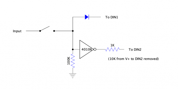
I'm not sure if that does what you want it to do. When the data enable switch is connected to GND, DIN1 is low and DIN2 is high,
which doesn't do anything so that would be ok I assume. Now if the data enable switch is connected to V+ (or not connected,
doesn't matter) and your data input is high then DIN1 is high and DIN2 is low. Which is the equivalent of pressing both the write
and erase button at the same time. I'll have to check the datasheet again to see what that does but I would think that you either
want to write a bit or erase a bit, not do both at the same time. If I ignore the CD4031 and just look at what would happen with
the output then U2c would be low, U2b would be high and as a result U2d and U2a would be low.
_________________
"My perf, it's full of holes!"
http://phobos.000space.com/
SoundCloud BandCamp MixCloud Stickney Synthyards Captain Collider Twitch YouTube |
|
|
Back to top
|
|
|
dk
Joined: Feb 12, 2019
Posts: 115
Location: Europe
|
| Posted: Thu May 20, 2021 2:01 pm Post subject:
|
|
|
Oh, you're right!
The momentary at the top is just the write switch. I was hoping (with the now-obviously incorrect bottom section) to be able to enable and disable the data input without interfering with the buttons. Do you have any ideas how to accomplish this? My first thought was to use a switch (4066), but I was trying to skimp on using an extra chip .... or perhaps I need to?
_________________
Horrors Of Dial-Up! on Facebook
Horrors Of Dial-Up! on Instagram |
|
|
Back to top
|
|
|
|

 Forum index » DIY Hardware and Software » Lunettas - circuits inspired by Stanley Lunetta