| Author |
Message |
Peppy
Joined: Feb 10, 2021
Posts: 30
Location: heide
|
 Posted: Sun Nov 28, 2021 11:13 am Post subject:
Yusynth VCO Bad waveform Posted: Sun Nov 28, 2021 11:13 am Post subject:
Yusynth VCO Bad waveform |
  |
|
Hello friends,
I built the Yusynth VCO (12V with SSM2210) and calibrated it on the keyboard without any problems!
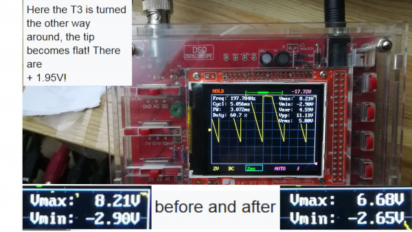
My problem is the T3 (10K Trimmer) "not responding", there is no change on the
Oscilloscope, I don't get +/- 5 volts for the saw, it is always -3V and + 7Volt, accordingly sine and triangle cannot be trimmed well.
The pulse wave seems to be good!
Can someone out there help and possibly know what the individual pin inputs and outputs of the ic`s should look like?
Grateful for any help!
Regards |
|
|
Back to top
|
|
 |
kkissinger
Stream Operator

Joined: Mar 28, 2006
Posts: 1471
Location: Kansas City, Mo USA
Audio files: 45
|
| Posted: Sun Nov 28, 2021 12:44 pm Post subject:
|
|
|
Often the source of problems on these modules are cold solder joints.
Check the solder joints on T3. Then, assure that T3's voltages swings from Negative voltage to ground.
In addition, check the solder connections for R24.
The Yusynth modules are excellent! Hope this helps.
_________________
-- Kevin
http://kevinkissinger.com |
|
|
Back to top
|
|
|
Peppy
Joined: Feb 10, 2021
Posts: 30
Location: heide
|
| Posted: Mon Nov 29, 2021 12:44 pm Post subject:
|
|
|
Hello, thanks for your answer! I checked all soldering points, no cold ones!
They wrote: "Then make sure that the voltages of T3 oscillate from negative voltage to ground"!
How do i measure this? Sorry I'm an amateur!
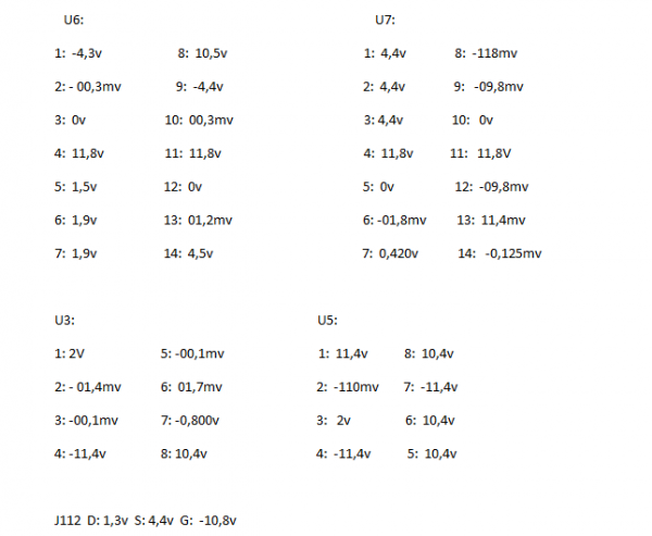
Here I still have some values from my ICs:
| Description: |
|
| Filesize: |
11.71 KB |
| Viewed: |
352 Time(s) |
| This image has been reduced to fit the page. Click on it to enlarge. |
|
| Description: |
|
| Filesize: |
11.71 KB |
| Viewed: |
372 Time(s) |
| This image has been reduced to fit the page. Click on it to enlarge. |

|
|
|
|
Back to top
|
|
|
kkissinger
Stream Operator
Joined: Mar 28, 2006
Posts: 1471
Location: Kansas City, Mo USA
Audio files: 45
|
| Posted: Mon Nov 29, 2021 7:48 pm Post subject:
|
|
|
| Peppy wrote: | | They wrote: "Then make sure that the voltages of T3 oscillate from negative voltage to ground"! |
You can check this with a voltmeter. Connect the ground of your voltmeter to the ground point on the circuit. Connect the other end to the wiper of T3.
When you rotate T3 you should see the (DC) voltage change from negative voltage to ground. Note that the negative voltage will only go about 2/3 of the way down to the negative supply voltage.
Again, if T3 has no effect, then check all the solder connections on T3 and R25.
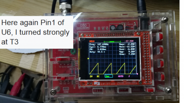
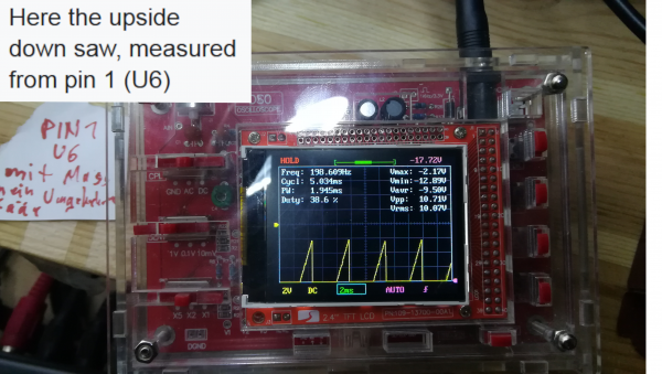
If this checks out, then use your oscilloscope to check the output at pin 1 of U6a. You should see an inverted sawtooth wave there. As you move T3, the bias of the waveform should change (the waveform should move up and down as you vary T3).
Check all the parts around U6a to be sure they are the proper values and that the solder joints are good. Make sure there are no solder bridges, too.
From your description of the problem, the inverting amp stage with its adjustable bias (T3) is the culprit. Particularly, if the value for R25 is wrong or if it has bad solder joints, the inverter will act like a comparator and will output a pulse wave (of sorts) but won't give you a nice sawtooth wave.
Hang in there!
_________________
-- Kevin
http://kevinkissinger.com |
|
|
Back to top
|
|
|
Peppy
Joined: Feb 10, 2021
Posts: 30
Location: heide
|
| Posted: Tue Nov 30, 2021 2:58 am Post subject:
vco |
|
|
Hi there,
Thank you for your description, I'll check everything carefully and get back to you! |
|
|
Back to top
|
|
|
Peppy
Joined: Feb 10, 2021
Posts: 30
Location: heide
|
| Posted: Tue Nov 30, 2021 4:58 am Post subject:
vco |
|
|
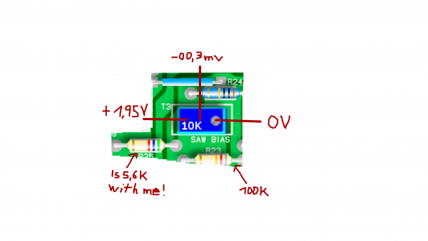
Send you pictures here in the hope that you will recognize my difficulty! My trimmers as well as R23 and R50 are socketed with me can simply take it out for test purposes!
| Description: |
|
| Filesize: |
863.73 KB |
| Viewed: |
381 Time(s) |
| This image has been reduced to fit the page. Click on it to enlarge. |
|
| Description: |
|
| Filesize: |
6.89 MB |
| Viewed: |
386 Time(s) |
| This image has been reduced to fit the page. Click on it to enlarge. |
|
| Description: |
|
| Filesize: |
7.24 MB |
| Viewed: |
398 Time(s) |
| This image has been reduced to fit the page. Click on it to enlarge. |
|
| Description: |
|
| Filesize: |
6.81 MB |
| Viewed: |
354 Time(s) |
| This image has been reduced to fit the page. Click on it to enlarge. |
|
| Description: |
|
| Filesize: |
7.03 MB |
| Viewed: |
368 Time(s) |
| This image has been reduced to fit the page. Click on it to enlarge. |
|
|
|
|
Back to top
|
|
|
Peppy
Joined: Feb 10, 2021
Posts: 30
Location: heide
|
| Posted: Tue Nov 30, 2021 9:08 am Post subject:
vco |
|
|
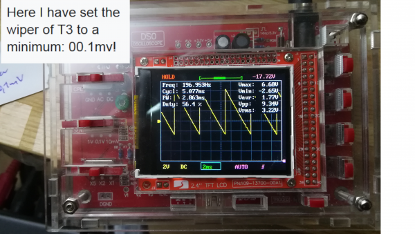
| I think something is wrong with the wiper, it's only -00.3mv, it seems to be suspiciously little, I will measure the value of the r25 again (unsolder one leg). I could also try 82K (R23) as yusynth suggested, or What do you think ? |
|
|
Back to top
|
|
|
kkissinger
Stream Operator
Joined: Mar 28, 2006
Posts: 1471
Location: Kansas City, Mo USA
Audio files: 45
|
| Posted: Tue Nov 30, 2021 11:34 am Post subject:
Re: vco |
|
|
| Peppy wrote: | | I think something is wrong with the wiper, it's only -00.3mv, it seems to be suspiciously little, I will measure the value of the r25 again (unsolder one leg). I could also try 82K (R23) as yusynth suggested, or What do you think ? |
Yes, the wiper should vary from 0v to around -7 volts.
_________________
-- Kevin
http://kevinkissinger.com |
|
|
Back to top
|
|
|
Peppy
Joined: Feb 10, 2021
Posts: 30
Location: heide
|
| Posted: Wed Dec 01, 2021 3:25 am Post subject:
VCO |
|
|
Hi there,
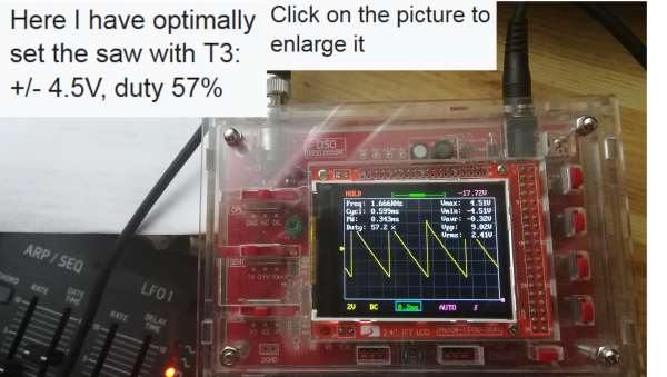
With your help I concentrated on the T3 and now noticed that the right side of R25 (5.6K) was short-circuited to the left side of the T3! Thanks for that ! I get a balanced saw, unfortunately the saw is broken again if I set the triangle well. There was a possibility for me to make all waves (Saw, Trianle, Sinus) look and sound good, but there were no 5v +/- in the waveforms, Sinus for example: 2v to 6.8v (total: 9v) I have with Sinus 1V too much? If so, could you possibly give me a hint where I could adjust a resistor?
Sorry that I write so much and annoy you |
|
|
Back to top
|
|
|
kkissinger
Stream Operator
Joined: Mar 28, 2006
Posts: 1471
Location: Kansas City, Mo USA
Audio files: 45
|
| Posted: Wed Dec 01, 2021 6:53 am Post subject:
|
|
|
Good work! Suggest you adjust to to get a good sawtooth then see if you can get a good sine and triangle by adjusting T4.
_________________
-- Kevin
http://kevinkissinger.com |
|
|
Back to top
|
|
|
Peppy
Joined: Feb 10, 2021
Posts: 30
Location: heide
|
| Posted: Wed Dec 01, 2021 9:14 am Post subject:
vco |
|
|
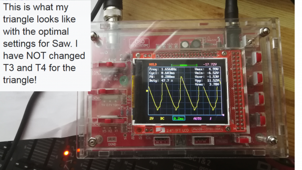
If the saw is good and perfect and I want to set the triangle with T3 and T4 next, then the saw will unfortunately be bad again, I never get a balanced +/- ratio on all shafts at the same time.
But I can make all waves look beautiful at the same time and they sound like they should, but then the ratio to +/- is wrong, for example triangle: + 2v -7.6v or saw with + 2.8v -7.4v, then they sound good and look good on the display, but as I said, then the plus-minus ratio is unfortunately not correct, a negative compensation has arisen for me. could I keep the asymmetrical relationship, or will there be difficulties with patching later?
Sorry, my English is not good and I have translated a lot of things automatically using google translate |
|
|
Back to top
|
|
|
kkissinger
Stream Operator
Joined: Mar 28, 2006
Posts: 1471
Location: Kansas City, Mo USA
Audio files: 45
|
| Posted: Wed Dec 01, 2021 9:03 pm Post subject:
|
|
|
Suggest that you adjust T3 to get a good sawtooth wave -- that is a good sawtooth wave without a DC offset.
Then see if you can adjust the other waveforms with T4 only.
When you do this, what is your voltage offset for the sine and triangle waves?
From your description, it sounds like the sine converter (U7d) is working ok. In addition, the triangle wave's inverting amp stage (U7c) is working ok.
T4 applies the offset voltage to the triangle wave. Note that the sinewave converter inverts the signal -- this is why the offset on the sine is reversed from the offset on the triangle.
Scrutinize your connections for R4 and R44. Make sure there is no solder bridge.
If that all checks out well, check the connections around U7b -- particularly R29 and R31. You should be finished with T3's adjustment. If you have a good sawtooth output (no offset) then T3 is ok.
Check for solder bridges -- particularly an unwanted short to the -15v or +15v that will introduce unwanted bias into your waveforms.
You are very close to solving this, in my opinion.
All the best!
_________________
-- Kevin
http://kevinkissinger.com |
|
|
Back to top
|
|
|
Peppy
Joined: Feb 10, 2021
Posts: 30
Location: heide
|
| Posted: Thu Dec 02, 2021 7:02 am Post subject:
vco |
|
|
Thank you for your feedback and for your patience!
I work with 12v (Eurorack module)!
I'll send you photos again here, should show how I checked / worked: and what results came out of it:
No short circuits on R4, R44, R29, R31!
U7 Pin1: 4.4V
Maybe you have another idea?
This vco is a
Affair of the heart, it sounds great!
| Description: |
|
| Filesize: |
6.45 MB |
| Viewed: |
273 Time(s) |
| This image has been reduced to fit the page. Click on it to enlarge. |
|
| Description: |
|
| Filesize: |
6.71 MB |
| Viewed: |
275 Time(s) |
| This image has been reduced to fit the page. Click on it to enlarge. |
|
| Description: |
|
| Filesize: |
6.4 MB |
| Viewed: |
262 Time(s) |
| This image has been reduced to fit the page. Click on it to enlarge. |
|
| Description: |
|
| Filesize: |
6.58 MB |
| Viewed: |
280 Time(s) |
| This image has been reduced to fit the page. Click on it to enlarge. |
|
| Description: |
|
| Filesize: |
6.02 MB |
| Viewed: |
272 Time(s) |
| This image has been reduced to fit the page. Click on it to enlarge. |
|
|
|
|
Back to top
|
|
|
Peppy
Joined: Feb 10, 2021
Posts: 30
Location: heide
|
| Posted: Fri Dec 03, 2021 12:59 am Post subject:
vco |
|
|
ok, sorry that i stole your time! Thank you for your help !
If anyone has an idea what I can do with my problem, please get in touch, even years later. I check here regularly. I will use the vco for the first time and hope that I will get it set correctly one day. Unfortunately, Yusynth is no longer available via e-mail
get in touch ! |
|
|
Back to top
|
|
|
kkissinger
Stream Operator
Joined: Mar 28, 2006
Posts: 1471
Location: Kansas City, Mo USA
Audio files: 45
|
| Posted: Fri Dec 03, 2021 6:05 am Post subject:
|
|
|
You might want to experiment with the value of R23.
The schematic has a note for R23: "choose value to achieve a satisfactory peak to peak range and a nice sine wave"
_________________
-- Kevin
http://kevinkissinger.com |
|
|
Back to top
|
|
|
Peppy
Joined: Feb 10, 2021
Posts: 30
Location: heide
|
| Posted: Sat Dec 04, 2021 5:58 am Post subject:
vco |
|
|
Hi there,
I tried R23, but going down to 82K or 68K only increases the overall "negative amplitube" in my opinion. No improvement by changing R23! I think any value that is responsible for triangle / sinus is not true!
I don't know if it's important I don't have an opa2137 yet, a TL072 and an LM311P no LM311N work for me, I ordered the parts, hope that could bring the change. |
|
|
Back to top
|
|
|
Psynth
Joined: Jul 18, 2018
Posts: 34
Location: UK
Audio files: 8
|
| Posted: Sat Dec 04, 2021 2:59 pm Post subject:
|
|
|
I noticed that the voltages at the power supply pins of your ICs are not consistent nor symmetrical. That is going to cause asymmetry in the waveshapes. Pins 4 and 8 of U3 and U5 should be at -11.8 and +11.8, as should pins 11 and 4 of U6 and U7.
I'd suggest looking carefully all over your power connections. Is anything getting hot?
Peter |
|
|
Back to top
|
|
|
Peppy
Joined: Feb 10, 2021
Posts: 30
Location: heide
|
| Posted: Sun Dec 05, 2021 11:25 am Post subject:
vco |
|
|
Hi there,
Thank you for your feedback signal !
I went through the IC again here News:
U6:
Pin1: + 0.95v 2: + 10mv 3: 0v 4: + 11.8mv 5: + 1v 6: + 1.9v 7: + 1.9v
Pin8: -2v 9: + 0.9v 10: -00.1mv 11: -11.9v 12: 0v 13: + 01.1mv 14: -0.9v
U7:
Pin1: + 4.4v 2: + 4.4v 3: + 4.4v 4: + 11.8v 5: 0v 6: -00.5mv 7: + 1.8v
Pin8: -0.51v 9: -0.3mv 10: 0v 11: -11.9v 12: -50mvv 13: -53mv 14: -0.58v
U5:
1: -11,4v 2:-108mv 3:+2v 4:-11,4v
5:+10,4v 6:+10,4v 7:-11,3v 8:+10,4v
... I think it should be ok!? That I, among other things, the 10.4v from the LM311 should also be ok, I remember it, even old forums report on the vco.
No component gets hot, not even the voltage regulator! |
|
|
Back to top
|
|
|
Psynth
Joined: Jul 18, 2018
Posts: 34
Location: UK
Audio files: 8
|
| Posted: Sun Dec 05, 2021 2:12 pm Post subject:
|
|
|
Well, I've not built this, so can't comment from experience, but given your problem seems to be that your waveform is not symmetrical about 0V, I was looking for any DC asymmetry. If the voltage output from the 78L12 is 10.4V too, then that might be OK.
Another possible issue is the voltage at pin 3 of U7 -according to the schematic, this (and therefore the voltage at pin 1) is meant to be +5V +/-2% ie between 4.9V and 5.1V, but your readings are +4.4V. The fact that Yves made that note suggests the value is quite critical. (Though I am not sure the calculations there are quite right. With R49 and R50 forming a 1/3 voltage divider, Vcc would have to be 15V to yield a 5V output, but the regulator only produces about 14.2V, which would produce 4.7V at pin 1.)
Still if you only have Vcc =10.4V, and are using 68k and 50k, you would expect just 4.4V (as you do), which may be too low. I'd suggest you try changing R50 to 60k or even a bit less, getting the output of U7 as close to 5V as you can. Actually setting R49 and R50 to the same value would yield 5.2V, which might be fine? |
|
|
Back to top
|
|
|
Peppy
Joined: Feb 10, 2021
Posts: 30
Location: heide
|
| Posted: Wed Dec 08, 2021 12:09 pm Post subject:
vco |
|
|
Thank you for your feedback signal !
I've changed R50 so that I get a perfect 5V. No significant improvement! Does it make sense to change R49? I finished building a second VCO very carefully, but it has the same symptoms! Maybe something is wrong with the parts list from Yusynth for the 12V circuit ???
Soon I'll get an OPA2134 to swap for the TL072!
In addition, I'll swap the LM311P for an LM311N, maybe that will bring some change.
I also have doubts about my oscilloscope, it may not be properly calibrated, I bought a new one that will arrive soon, because my oscilloscope that I have here also shows my Behringer Neutron (desktop synthesizer) on a saw , Sinus, Triangle an imbalance at Vmax. + And Vmin.- an.
It's bewitched |
|
|
Back to top
|
|
|
Peppy
Joined: Feb 10, 2021
Posts: 30
Location: heide
|
| Posted: Fri Dec 10, 2021 4:14 am Post subject:
vco |
|
|
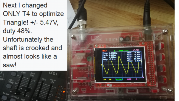
Hello folks,
want to let you guys know everything that i most likely finally found the bug. I received my new oscilloscope today, the waveforms have immediately improved by 80%, sine and triangle are balanced, saw ok too! I will still work on the resistors that I have changed in order to optimize it even further and I am full of hope that I will get it to work well.
Conclusion: do not buy a china oscilloscope (do not buy a copy of the DSO-138)!
I am happy
Thank you for your help ! |
|
|
Back to top
|
|
|
Peppy
Joined: Feb 10, 2021
Posts: 30
Location: heide
|
| Posted: Fri Dec 10, 2021 10:16 am Post subject:
vco |
|
|
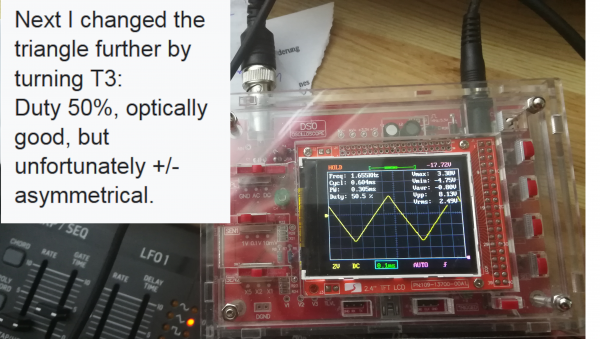
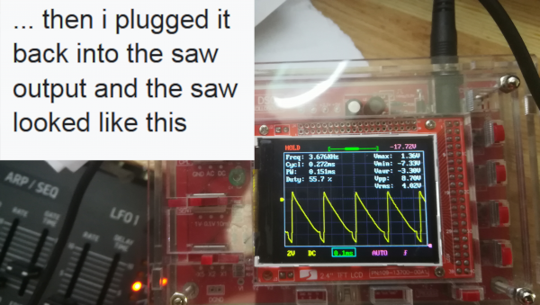
| Not much is missing from perfect waveforms! I can increase / control the positive voltage with the R50, R49 and R23, but where can I control the negative voltage to the saw? someone an idea? With the R25? |
|
|
Back to top
|
|
|
|

 Forum index » DIY Hardware and Software » YuSynth


